GunnsElectUserLoad - nasa/gunns GitHub Wiki
These are GUNNS Spotter classes that provide a flexible interface between vehicle equipment models and the electrical circuit that powers them. These can be used as the electrical aspect of equipment such as valve controllers, pump motors, heaters, etc.
There are currently two variants of User Load Spotters that you can use:
- GunnsElectResistiveUserLoad: models a resistive load.
- GunnsElectConstantPowerUserLoad: models a constant-power load.
You'll find these in the gunns/draw/libraries/GUNNS_Spotters.xml shape library. Because these classes are GUNNS spotters, not links, they don't have ports or associated port connection rules. They do have configuration and input data, which are discussed below.
You can also define these spotters in any other class, not just GunnsDraw networks. This can be useful to group the user loads for a particular subsystem model into its own "electrical aspect" class. Since it only contains user loads, and not an actual circuit, this electrical aspect class doesn't need to be a GUNNS network.
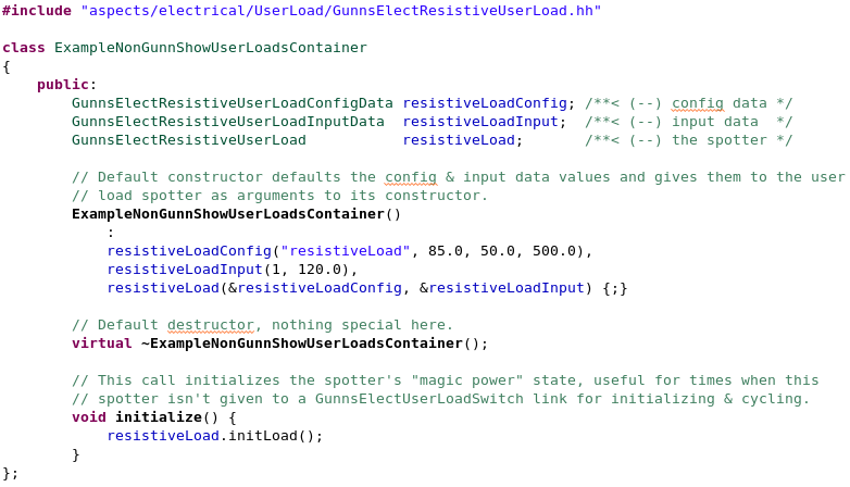
The spotter is initialized and cycled in run-time by the object that points to it, such as a GunnsElectUserLoadSwitch link. However, you also have the option of not pointing to it at all; in this case the spotter isn't cycled in run-time, and its outputs to its interfaced subsystem models are constant. This "magic power" mode is useful for when you have a model that needs an ideal power flag from the spotter, without actually connecting the spotter to an electrical network. Some of the spotter's input data, detailed below, sets up these output terms to their desired magic power values. However for this to work, the spotter still must be initialized by something. Since in this case there's no GunnsElectUserLoadSwitch link to initialize it, another option is for the spotter's container class to do it. Therefore, when creating these custom electrical aspect container classes, it's always a good idea to call the spotter's initLoad method to provide for the magic power option.
Below is an example of how this kind of electrical aspect container class would be coded:
ConstructorArgs Parameter:
- This should be: &netConfig.THIS_NAME, &netInput.THIS_NAME, where THIS_NAME is replaced with the actual instance name of the spotter object. This tells the spotter object where to find its configuration and input data in the network.
Configuration Data Parameters:
- underVoltageLimit (default = 0.0 (ohm), must be >= 0): This is the minimum voltage for which the user load will output a True power valid flag to the interfaced subsystem model.
- resistanceNormal or powerNormal (default = 0.0 (ohm or W), must be >= 0): This is the default resistance or power load of the resistive or constant-power user load, respectively, when it is in the LoadON mode.
- resistanceStandby or powerStandby (default = 0.0 (ohm or W), must be >= 0): This is the default resistance or power load of the resistive or constant-power user load, respectively, when it is in the LoadSTANDBY mode.
- fuseCurrentLimit (default = 0.0 (amp)): this is the electrical current limit above which the fuse trips.
- dutyCycleFraction (default = 0.0, must be in (0-1)): this configures the fraction of time the user load is in the ON state in the optional automatic duty cycle function. This function, when enabled, drives the user load's state to alternate between ON and OFF over the given period. When enabled, this takes over the user load's state and prevents other models from driving it.
- dutyCyclePeriod (default = 0.0 (s)): this configures the duration of each cycle in the optional automatic duty cycle function. Setting this > 0 enables the function. Setting it = 0 disables the function and allows other models to drive the user load's state.
Input Data Parameters:
- initialMode (default = 0): This is the initial mode the user load is in. Here you can use either integer values 0, 1, 2, or the enumerated equivalents: LoadOFF, LoadON, LoadSTANDBY respectively.
- initialVoltage (default = 0 (v), must >= 0): This is the initial voltage input to the user load from its power supply. In the "magic power" case, this value persists as a constant voltage output to interfaced models.
- dutyCycleTimer (default = 0 (s)): This is the elapsed time in the initial duty cycle. When the duty cycle function is enabled, the timer increments over the given dutyCyclePeriod. This is the initial value of that timer at the sim start. When the duty cycle function is enabled, the load is in the ON state for the first dutyCycleFraction of each cycle, and is OFF for the remainder of the cycle.
- N/A
- N/A