GunnsElectPvString - nasa/gunns GitHub Wiki

This link models one photovoltaic cell or multiple cells wired in series. A solar panel typically consists of several strings wired in parallel; thus several of these links can be used in parallel in a network to model a solar panel.
This link models the string as an equivalent circuit of components. It has an interface to an environment model for including the effects of ambient light source power, facing & shading. It models the effects of cell temperature.
This link models some diodes in series with the cells: a final blocking diode after the furthest downstream cell, and bypass diodes around groups of cells. The blocking diode prevents backflow of current into the string from a higher-voltage downstream circuit. The bypass diodes allow some functioning of the string when it is partially shaded, by bypassing current from lit cell groups around shaded cells groups. The total number of cells in the string and the number of cells in each bypass diode group are configurable.
Degradation of the string due to age and surface fouling can be modeled by using the blockage malfunction in the mSourceLink. This link's own blockage malfunction is not used. Bypass of cell groups is normally caused by shading, but can also be forced with the cell group failure malfunction in this link.
For best results, there should be some kind of regulator downstream of the string to regulate its output voltage, current & power as needed by the circuit.
The GunnsElectPvString link can be attached to nodes in the same ways that a GunnsBasicConductor can. The picture below shows the suggested way to connect a GunnsElectPvString:
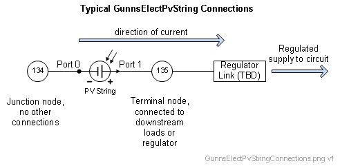
Port Connection Rules (These are limitations on the port connection to nodes that the link enforces in run-time):
- Ports 0 and 1 cannot connect to the same non-Ground node.
Other Rules (These are extra rules you should always try to follow):
- Port 0 is the internal junction node of the cell equivalent circuit and should not be connected to any other links in the network.
- Port 1 is the output terminal node supplying power to the downstream circuit. This node can be shared with other strings in parallel, depending on the design of the regulator.
- Since Port 0 should not be connected to any other links, you should not connect multiple of these links in series.
Configuration Data Parameters:
- surfaceArea (default = 0.0 (m2), must be >=0): This is the total surface area of all the cells in the string. This only counts one side of the panel, not both.
- backsideReduction (default = 0.0 (--), must be (0-1)): This is the amount of reduction of power generation when the cells are lit from the back side. A value of zero allows the cells to generate the same power from either side. A value of 1 limits the cells to only generate power when lit on the front side, and can generate no power from the back side.
- sourceAngleExponent (default = 0.0 (--), must be (0-10)): This is an exponent on the cosine function of the light source angle relative to the panel. The string produces power in proportion to cosexponent(angle). An exponent value of 1 creates a normal cosine curve. A lower value allows more power to be generated at off angles, whereas a higher value causes a larger fall-off of power with increasing off angle.
- cellEfficiency (default = 0.0 (--), must be (0-1)): This is the fraction of light power that is converted to electrical power by the cells. This does not include the losses in the shunt and series equivalent resistances. Typical values of real solar cells are around 0.2.
- cellSeriesResistance (default = 0.0 (ohm), must be >0): This is the equivalent series resistance of each cell. A typical value for a cell is around 0.017 ohm.
- cellShuntResistance (default = 0.0 (ohm), must be >0): This is the equivalent shunt resistance of each cell. A typical value for a cell is around 200 ohm.
- numCells (default = 0 (--), must be >0): This is the number of cells in the string. A value of 1 models a single cell, and values >1 models a string of cells wired in series.
- bypassDiodeInterval (default = 0 (--), must be divisible in numCells): This is the number of cells in each bypass diode group. If it is not desired to model any bypass diodes, then set this number equal to numCells. This must be at least 1 and cannot be larger than numCells. The number of bypass groups in the string will be numCells divided by this number.
- bypassDiodeVoltageDrop (default = 0.0 (v), must be >=0): This is the diode junction voltage drop across each bypass diode. Silicon diodes typically have a value of 0.6.
- blockingDiodeVoltageDrop (default = 0.0 (v), must be >=0): This is the diode junction voltage drop across the blocking diode. Silicon diodes typically have a value of 0.6.
- refTemperature (default = 0.0 (K), must be >0): This is the reference temperature for temperature effect calculations. Temperature effects will be proportional to the difference between the actual panel tempeature during run-time, and this reference value.
- temperatureVoltageCoeff (default = 0.0 (1/K)): This is the coefficient for the effect of temperature on open-circuit voltage of the cells. Typical solar cells have a value of -0.003 (1/K), which decreases open-circuit voltage by 0.3% per degree Kelvin.
- temperatureCurrentCoeff (default = 0.0 (1/K)): This is the coefficient for the effect of temperature on short-circuit current of the cells. Typical solar cells have a value of 0.00065 (1/K), which increases short-circuit current by 0.065% per degree Kelvin.
Input Data Parameters:
- sourceFluxMagnitude (default = 0.0 (W/m2), must be >= 0): Initial value of the light source flux, or surface power per unit area at the string's location. This would normally be driven in run-time from a radiative environment model, but can be initialized here. This initial value is also stored by the model as its reference for updating a percent insolation term, to indicate to users how much sunlight is on the panel during run-time. A good reference value is the mean solar flux in low-earth orbit = 1361 W/m2.
- sourceAngleFromNormal (default = 0.0 (r)): Initial angle between the panel surface normal vector and the vector to the light source. A value of 0 is directly face-on the panel and creates the most power. A value of +/- pi/2 is edge-on and creates no power. Values greater than +/- pi/2 put the light source behind the panel (back lit).
- sourceExposedFraction (default = 0.0 (--), must be (0-1)): Initial fraction of the panel surface that is visible to the light source. Any value less than 1 means the panel is partially shaded and produces less power. A value of 0 makes the panel completely shaded and can produce no power.
- temperature (default = 0.0 (K), must be >0): Initial temperature of the panel for calculating the temperature effects.
- N/A
- N/A