GunnsElectIps - nasa/gunns GitHub Wiki

Background
This models an Internal Power Supply (IPS) for a device such as a controller or computer. It chooses from a set of available power input feeds, determines whether there is sufficient voltage to power the device, outputs the powered-on state to an external model of the device, and puts the device's constant power load on the chosen input feed. It has two different sets of logic to choose the input feed, and malfunction models to fail any or all of the power inputs.
How To Use in GunnsDraw
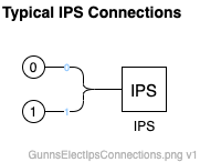
This is a variable port link. Port 0 is required at a minimum, and additional ports 1+ are for backup power supply inputs. For example, an IPS that has two power inputs would have 2 ports in this link, 0 and 1.
Port Connection Rules
These are limitations on the port connection to nodes that the link enforces in run-time:
- All ports must connect to different nodes, unless it is the network Ground node.
The picture below illustrates an example setup and connections in the network. This is an example of a 2-port IPS.
Configuration Data Parameters:
- backupPowerImplemented (default = false): This boolean determines the type of input selection logic this IPS uses. When false, the IPS will prefer whichever input has the highest voltage. When true, it will prefer the port 0 input as its primary input, with the other ports as backups.
- powerConsumedOn (default = 0 (W), must be >= 0): This is the constant-power load that the IPS will place on the selected input when it has sufficient voltage.
- auxillaryOnePowerOn (default = 0 (W), must be >= 0): This is the first of two optional extra constant-power loads the IPS will place on the selected input when it has sufficient voltage.
- auxillaryTwoPowerOn (default = 0 (W), must be >= 0): This is the second of two optional extra constant-power loads the IPS will place on the selected input when it has sufficient voltage.
- underVoltageLimit (default = 0 (V)): This is the minimum voltage that the selected input must have in order for the IPS to output its power valid indication.
- backUpVoltageThreshold (default = 0 (V)): This is only used when backupPowerImplemented is true. If the primary input drops below this voltage, the IPS will attempt to switch to a backup input.
- potentialOnTolerance (default = 0 (V)): This is how much higher another input's voltage has to be than the current selected input in order to switch to that higher voltage input. This prevents some chattering between inputs if their voltages are close to each other.
- thermalFraction (default = 0.0 (0-1)): This is the fraction of the total power load that is output as waste heat.
- backupVoltageMin (default = 0 (V)): This is the minimum voltage a backup input can have (when backupPowerImplemented is true) in order for it to be selected.
- backupVoltageMax (default = 0 (V)): This is the maximum voltage a backup input can have (when backupPowerImplemented is true) in order for it to be selected.
- conductanceTolerance (default = 0 (1/ohm)): This is the minimum change in load conductance to affect the network. The constant-power load is applied to the network as a conductance from the input port to Ground, with conductance G = P/VV, where P is the desired constant-power load and V is the input port voltage. Noisy input V creates noisy load conductance, which can lead to excess iterations needed to converge the network solution. The change in G must be higher than this tolerance to before the actual load conductance is updated to the new G value. Higher values in this tolerance can reduce the number of iterations (minor steps) in the network, but lower values result in more accurately applying the desired constant-power load. We recommend you leave this zero unless you have problems with the network failing to converge.
- convergedFrameToCheckVoltage (default = 1): This term is not used and has no effect. You can leave this alone.
- numberOfVoltageSwitchesInASolution (default = 1): This is the limit on the number of times the IPS can switch input ports in one major step of the network. Depending on the rest of this link's configuration and the larger network setup, the IPS can keep chattering between multiple inputs: switching to a backup input loads it down and can cause it to drop below the previous input, causing the IPS to want to switch back to the previous input, and so on. This value limits the number of times that can occur. We recommend a value of 1 in most cases.
- commandOnUsed (default = false): This flag tells the IPS whether it should operate in response to a separate input command (the link's mCommandOn flag). When commandOnUsed is true, the IPS will only operate and output valid power when mCommandOn is set. When false, the IPS will operate and update its output power valid flag at all times.
- unselectedInputConductance (default = 0 (1/ohm)): this is the load conductance that is placed on unselected input ports. This can model small 'leak' loads to sensors monitoring the unused inputs, etc.
Input Data Parameters:
- malfBlockageFlag (default = false): This has no effect. The 'blockage' malfunction is not implemented in the IPS link.
- malfBlockageValue (default = 0): This has no effect. The 'blockage' malfunction is not implemented in the IPS link.
Common Problems:
Chattering between input ports: see the description of this problem in numberOfVoltageSwitchesInASolution above. This can appear as some combination of the following signatures:
- Excessive flipping of the chosen input port shown in the link's mActivePowerSource term
- Voltages fluctuating across 2 or more of the link's power feed inputs
- Excessive minor steps to converge the network, visible in the network solver's mLastMinorStep term
- The network failing to converge due to the minor step limit being exceeded. This will output repeated error messages to the Health & Status log, the network solvers mConvergenceFailCount term will be incrementing, and the electrical state of the network will appear to freeze in place and become unresponsive to changing inputs.
There are several ways to avoid or alleviate this problem:
- Set the numberOfVoltageSwitchesInASolution to a lower value (but no lower than 1), as described above. This doesn't prevent the oscillation, but it can limit how many minor steps the oscillation spans over, and keep the network converging.
- Reduce the power load applied to the selected input. This is the sum of powerConsumedOn, auxillaryOnePowerOn and auxillaryTwoPowerOn.
- Reduce the voltage sag on the selected input in response to the load. The voltage sag is typically proportional to the resistance of the upstream circuit and voltage supply.
- Use the backup power switching method (backupPowerImplemented = True).
- While using the back power switching method, increase the voltage band between the setpoint below which the IPS will start looking for another input (backUpVoltageThreshold) and the minimum voltage in the other input to receive the selection (backupVoltageMin).
References:
- N/A