GunnsElectBattery - nasa/gunns GitHub Wiki

This extends GunnsBasicPotential to model a simple electrical battery in GUNNS networks. It creates a voltage rise across the attached basic nodes, similar to a GunnsBasicPotential, except that the voltage produced is a function of the battery's State of Charge (SOC). The battery contains one or more cells, arranged either all in parallel or all in series. Each cell has an internal resistance, a maximum charge capacity, and a State of Charge (SOC). The SOC drops as the cell is discharged, and rises as the cell is charged.
Like the Basic Potential, the battery has an internal resistance causing a drop in the voltage rise under load. This internal resistance is the (parallel or series) combination of the cells' internal resistances, and a total interconnect resistance of the interconnection wiring between all cells.
The open-circuit voltage (Voc) of each cell is modeled as a table-lookup function of the cell's SOC. The total Voc of the battery is the (parallel or series) combination of all of the cells' Voc.
SOC Voc Table
Batteries must be configured with a Data Table object that defines Voc of a single battery cell as a function of SOC. The Data Table object can be dragged & dropped into your network container from the GUNNS_Generic.xml shape library just like other shapes. When you drop a Data Table into your network, you can expand it by clicking the '+' symbol in the left-hand side of its title bar. This is illustrated below:
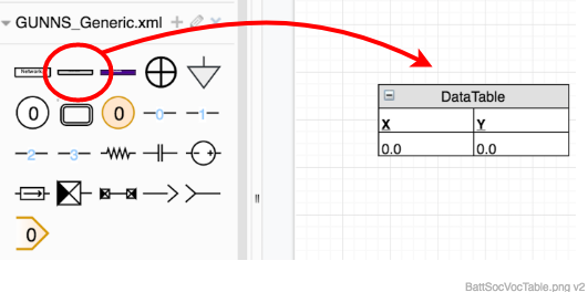
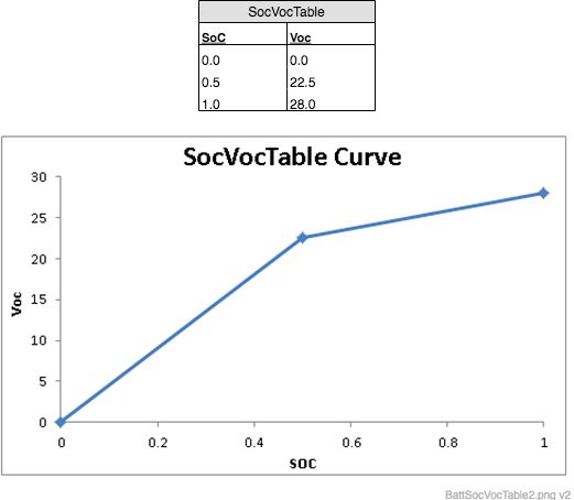
The name of the table instance is in the gray title bar. You can change it by selecting the table and typing the new name. Optionally, you can edit the 'X' and 'Y' data column labels to be 'SoC' and 'Voc' or similar, for clarity. Then, insert data rows and edit their values to create the Voc vs. SOC function. You can insert rows by selecting a row, then typing <Ctrl+Enter>, and you can delete rows by selecting a row and typing <Delete> or <Backspace>. The result is a table of SOC values for which the Open Circuit Voltage (Voc) values will be looked up. The SOC values should range from 0.0 to 1.0 for best results. The model uses a linear interpolation between data points. Make sure you put the SOC values in the left-most column. Here we have defined 3 points in our table, for a battery cell with nominal 28 Vdc at full charge. We plot what the resulting linear interpolated curve of Voc as a function of SOC looks like:
These Data Tables can be shared among several batteries (see how they're used below).
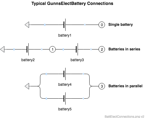
Batteries can be hooked up to nodes the same ways as GunnsBasicConductor can. Port 0 is the negative terminal and Port 1 is the positive terminal. This picture shows the typical ways that batteries are connected:
Port Connection Rules (These are limitations on the port connection to nodes that the link enforces in run-time):
- Both ports cannot connect to the same non-Ground node.
Other Rules (These are extra rules you should always try to follow):
- N/A
Configuration Data Parameters:
- numCells (default = 0, must be > 0): The number of cells in this battery.
- cellsInParallel (default = false): Whether the cells are stacked in parallel (true) or series (false). When in series, the total Voc of the battery will be the sum of all the individual cells' Voc values. When in parallel, the Voc of the battery will be that of the cell with the highest Voc.
- cellResistance (default = 0 (ohm), must be >= 0): The internal resistance of each cell.
- interconnectResistance (default = 0 (ohm), must be >= 0): The total resistance of all interconnect wiring between the cells. The total internal resistance of the battery is the (parallel or series combination) resistance of all the cells, plus this interconnect resistance.
- maxCapacity (default = 0 (amp*hr), must be > 0): The total capacity of the battery when all cells are at 1.0 SOC. The SOC will decrease as current is drawn through the battery, and when this value of (amp*hr) total charge has been drawn, the SOC will reach 0. Often you will have the capacity for your battery given in W*hr or kW*hr. A good way to convert this to amp*hr is to (first convert your kW*hr value to W*hr if needed) divide the W*hr value by the product of numCells and the integral of the mSocVocTable curve.
- mSocVocTable (default = 0 must not be 0): This is the address of an Data Table object in the drawing, described above. The proper syntax for this is: &network->(Data Table name). For example, using the table illustrated above wouyd be: &network->SocVocTable
Input Data Parameters:
- malfBlockageFlag: same as GunnsBasicConductor.
- malfBlockageValue: same as GunnsBasicConductor.
- soc (default = 0.0, must be (0-1)): Initial State of Charge of the battery and each individual cell.
- malfThermalRunawayFlag (default = false): This sets the initial active state of the thermal runaway malfunction. This malfunction starts a thermal runaway effect in all of the battery cells. It starts with cell 0 and chains to each successive cell in order.
- malfThermalRunawayDuration (default = 0 (s)): This sets the time that each cell takes to convert its stored energy into heat during its thermal runaway.
- malfThermalRunawayInterval (default = 0 (s)): This sets the interval between the start of the runaway in each cell.
- N/A
- N/A