GunnsBasicFlowController - nasa/gunns GitHub Wiki

This link extends GunnsBasicConductor with the ability to control a constant flux (electrical current or thermal heat flux) through the conductor. It modulates its internal conductance G according to:
where I is the desired flux (current) and V is the potential (voltage) drop across the link. As the potential drops, the link increases G to maintain the constant I, and so on. The link is configured with a maximum conductance that the device can reach, which helps network stability and avoids dividing by zero when the potential drop is very small.
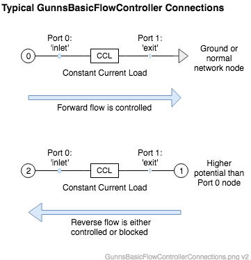
The link has options for how it handles flow in the reverse direction. As with all conductors, flow can only go from higher to lower potential. As shown in the diagram below, forward flow is defined in the direction from the link's Port 0 ("inlet") to Port 1 ("exit"). Forward flow is always controlled as described above. For reverse flow, the link can be configured to either control it in the same manner as forward flow, or to block it altogether. Bocking reverse flow would be equivalent to placing a diode in the forward direction, so this saves you from having to add a separate diode link in series.
The link can be configured to operate in either "linear" or "non-linear" network modes. More info on this in the nonLinear configuration data description below.
This link has the same connection rules as GunnsBasicConductor. The picture below shows how it is typically used:
Port Connection Rules (These are limitations on the port connection to nodes that the link enforces in run-time):
- Same as GunnsBasicConductor.
Other Rules (These are extra rules you should always try to follow):
- Same as GunnsBasicConductor.
Configuration Data Parameters:
- defaultConductivity: Same as GunnsBasicConductor. This sets the maximum conductance the link can reach when it is controlling current. It is the maximum G in G = I/V.
- nonLinear (default = false): This sets whether the link acts like a linear (false) or non-linear (true) link. Typically you will want to use non-linear for electrical networks and linear for thermal networks. Non-linear allows the link to keep adjusting its conductance G during every minor step in the non-linear network's minor step loop, so that the link's conductance and flow will converge to the desired flow as the network converges to its solution during every major step. In other words, the flow appears to instantly control to the desired value. Linear networks cause a slower, more observable convergence to the desired flow rate over several network major steps.
- enableReverseControl (default = false): This sets whether the link controls (true) or blocks (false) flow in the reverse direction.
Input Data Parameters:
- malfBlockageFlag: Same as GunnsBasicConductor. This malfunction combines with the flux override malfunction described below, and further reduces the actual flux through the link.
- malfBlockageValue: Same as GunnsBasicConductor.
- malfFluxFlag (default = false): This sets the initial active (true) or inactive (false) state of the link's flux override malfunction. When active, the link controls to the malfunction rate value instead of the normal rate command input.
- malfFluxValue (default = 0.0): This initializes the flow rate value for the malfunction.
- fluxCommand (default = 0.0): This initializes the desired flow rate value for link to control to. Positive or negative value can be given, but the link always uses its absolute value and flow can only go in the direction from higher to lower potential.
- N/A
- N/A