GunnsBasicExternalDemand - nasa/gunns GitHub Wiki

This class inherits GunnsBasicPotential, and is used in tandem with the GunnsBasicExternalSupply class to flow between two separate electrical or thermal networks, with this class applying potential (voltage or temperature) from the external supply-side network to our local demand-side network as a potential source and calculating a demand flux (current or heat flux) to apply to the supply network.
Note: for interfaces between electrical networks, we recommend using the GunnsElectConverterInput and GunnsElectConverterOutput links instead, as their interface will be more stable.
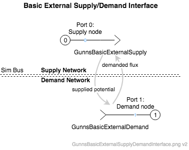
This picture shows how to hook up the GunnsBasicExternalDemand in the local network and the GunnsBasicExternalSupply link in the external network and the simbus interfaces between the networks. The arrowheads in the supply & demand link shapes imply a flow direction from the supply node to the demand node, but in fact flow can go in either direction, and always flows from the higher-potential side to the lower-potential side, as a regular conductor would. The arrowheads simply indicate the direction of positive flow values.
Port Connection Rules (These are limitations on the port connection to nodes that the link enforces in run-time):
- Port 0 must always be attached to Ground. This port is optional. If not drawn, GunnsDraw will automatically connect it to the Ground node.
- Port 1 cannot be attached to Ground.
Other Rules (These are extra rules you should always try to follow):
- The demand node must NOT be capacitive, so don't put any capacitor links on that node.
- The demand link should be used in the network with the smaller local capacitance - which is usually the network that has the smaller nearby capacitance or potential source.
- In general, the interface location should be chosen where the supply network has a large nearby capacitance relative to the demanded flow rates. In other words, a location where typical interface flow rates will result in small potential changes in the supply network. Such an interface is called "loosely coupled" because the demand network can't really affect the supply network. Loosely coupled interfaces are more stable. "Tightly coupled" interfaces, where even small demand flow rates cause large changes in the supply potential, are very unstable and should be avoided whenever possible.
- First test the interface for stability before modifying the stability filter configuration parameters (see below). Most supply/demand interfaces, when chosen in a loosely-coupled location, work fine with the default values.
Configuration Data Parameters:
- defaultConductivity: Same as GunnsBasicConductor.
- In order to improve stability, the demand link can filter its effective conductivity based
on the capacitance of the supply network. This demand link attempts to estimate the supply
network capacitance using a filter based on the last 2 pass data trends accounting for simbus
lag. The estimated capacitance results in a new value for this link's effective conductivity,
using these 3 config parameters:
- filterMinConductivity (default = 1.0, must be >= 0.0): Recommend using the default value.
- filterMinDeltaP (default = 1.0E-8, must be >= 0.0): Recommend using the default value.
- filterCapacitanceGain (default = 0.05, must be (0-1)): Recommend using the default value.
Input Data Parameters:
- malfBlockageFlag (default = false): Initial state of the blockage malfunction activation flag. This malfunction cuts off the potential source to the demand node. A value of 1.0 completely isolates the supply & demand networks from each other.
- malfBlockageValue (default = 0.0, must be (0-1)): Initial state of the blockage malfunction activation value.
- sourcePotential (default = 0.0): Base class attribute which is not used and should be left zero.
-
Potential/flow oscillations: Oscillations in supply potential and demand flow are very bad to have because
they typically can go unconverged and can blow up both networks. This is the biggest stability risk when interfacing
networks with these links. This usually occurs in locations where the interface is too tightly coupled, i.e. not enough capacitance
on the supply node. Try remedying a problem in this order:
- First, make sure you are following the rules for using supply & demand links (see above).
- Find a more loosely-coupled location to apply the interface.
- Increase the capacitance on the supply node. This is usually not the best option because it can add unrealistic capacitance to your system. Or,
- Decrease the conductivities of links that attach the demand node to the rest of the demand network. This reduces the coupling between the networks at the expense of higher and possibly unreaslistic delta-potential across the interface and reduced flow rates.
- As a last resort, use the blockage malfunction with increasing values to de-couple the networks.
- N/A