ConverterElect - nasa/gunns GitHub Wiki

Note: this link is obsoleted by the GunnsElectConverterInput and GunnsElectConverterOutput links.
This link models a voltage converter and output regulator. A voltage on the input side (say 120 Vdc) is converted to a different regulated voltage on the output side (28 Vdc or 220 Vdc, etc.) The output voltage can be higher or lower than the input.
The link acts as a voltage source on the output side, which creates the regulated output voltage. On the input side, the link acts as a power load on the upstream circuit. A converter efficiency is modeled, which adds more power demand on the input in addition to the power demanded by the output side. The converter also models a 'standby power', which is a power draw on the input when the converter is on but has no output load.
The link models several types of trips in which the converter will switch off when these conditions occur: Input Under-Voltage, Input Over-Voltage, Output Over-Current and Output Over-Voltage. These can be individually configured, or inhibited to bypass the trip functionality when not needed.
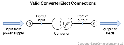
This picture shows how to connect the ConverterElect link to nodes:
Port Connection Rules (These are limitations on the port connection to nodes that the link enforces in run-time):
- Ports 1 and 3 can only be connected to the Ground node. These ports are optional. If not drawn, like in the example above, GunnsDraw will automatically connect them to the Ground node.
Other Rules (These are extra rules you should always try to follow):
- N/A
Configuration Data Parameters:
- outVoltageSensorConfig (default = &convVoltSensorConfig, must != NULL): This is the address of a SensorAnalog configuration object in the network. This configures a built-in sensor that gets the sensed voltage for use in the converter's Output Over-Voltage trip logic. Even though the trip logic is optional, a sensor configuration must always be supplied here. So for example, to use a sensor object named VoltSensor7 in the drawing, this config data would be &VoltSensor7Config.
- outCurrentSensorConfig (default = &convCurrSensorConfig, must != NULL): Similar to outVoltageSensorConfig above, this configures a built-in sensor used for the Output Over-Current trip logic.
- outputConductance (default = 100.0 (1/ohm), must be >= 0): This is the conductance of the output-side voltage source when the converter is on. This models the internal resistance of the non-ideal voltage supply, just like in a battery. Higher values make the output supply more ideal, i.e. it drops less under load, and lower values make the output voltage drop more under load. A value of zero disables the output voltage supply.
- converterOffConductance (default = 1e-6 (1/ohm), must be >= 0): This is the conductance of the output-side voltage source when the converter is off. A value > 0 grounds the output circuit when the converter is off.
- tripPriority (default = 3, must be >= 0): this sets the trip priority of this link's trip logic relative to other links in the network. Network links do their trip checks in order of priority, so that circuit trips will happen in the correct location. Lower priority numbers go first.
- standbyPower (default = 60 (W), must be >= 0): this defines the power used by the converter when it is on but there is no output load. This power is added as a constant-power load on the input side.
Input Data Parameters:
- malfBlockageFlag (default = false): Initial state of the blockage malfunction activation flag. This link does not implement a blockage malfunction so this term is ignored.
- malfBlockageValue (default = 0.0, must be (0-1)): Initial state of the blockage malfunction activation value. This link does not implement a blockage malfunction so this term is ignored.
- outVoltageSensorInput (default = &convVoltSensorInput, must != NULL): Just like outVoltageSensorConfig above, this is the input data for a built-in sensor used for the Output Over-Current trip logic. In the above example using a sensor object named VoltSensor7, this input data would be &VoltSensor7Input.
- outCurrentSensorInput (default = &convCurrSensorInput, must != NULL): Similar to outVoltageSensorInput above, this is the input data for a built-in sensor used for the Output Over-Current trip logic.
- malfOpOverCurrentFlag (default = false): Initial state of the Output Over-Current limit malfunction activation flag.
- malfOpOverVoltageFlag (default = false): Initial state of the Output Over-Voltage limit malfunction activation flag.
- malfRegulatedVoltageFlag (default = false): Initial state of the regulated output voltage malfunction activation flag.
- inputVoltage (default = 124.5 (v)): Initial value of the input voltage supplied to the converter. If you want the converter to start the sim in the on state, set this to a good supply voltage to avoid the converter tripping off when you go to run.
- regulatedVoltage (default = 28.0 (v), must be < outputOverVoltageLimit): This configures the ideal regulated output voltage of the converter.
- efficiency (default = 0.9, must be within (0-1)): This configures the conversion efficiency of the converter. Lower efficiency adds more power demand on the input in addition to the power demanded by the output side.
- outputOverCurrentLimit (default = 5.0 (amp)): This configures the output current limit above which the Output Over-Current trip will occur.
- outputOverVoltageLimit (default = 32.0 (v), must be > regulatedVoltage): This configures the output voltage limit above which the Output Over-Voltage trip will occur.
- outputOverCurrentTripActive (default = false): This enables (true) or disables (false) the Output Over-Current trip logic in the converter.
- outputOverVoltageTripActive (default = false): This enables (true) or disables (false) the Output Over-Voltage trip logic in the converter.
- inputOverVoltageLimit (default = 132.0 (v), must be > inputUnderVoltageLimit): This configures the input voltage limit above which the Input Over-Voltage trip will occur.
- inputUnderVoltageLimit (default = 93.0 (v), must be < inputOverVoltageLimit): This configures the input voltage limit under which the Input Under-Voltage trip will occur.
- inputOverVoltageTripActive (default = false): This enables (true) or disables (false) the Input Over-Voltage trip logic in the converter.
- inputUnderVoltageTripActive (default = false): This enables (true) or disables (false) the Input Under-Voltage trip logic in the converter.
- N/A
- N/A