Communications Between Aux and Main MCU - mooltipass/minible GitHub Wiki
The auxiliary and main microcontrollers can communicate with each other using a serial link (LSB first).
While the main role of the auxiliary MCU is to receive/send data packets from/to USB or Bluetooth, other types of messages (firmware update, keyboard HID presses) are also needed.
Message Structure and Serial Link Specs
The fixed length 560 bytes long message structure is defined as follows:
from aux MCU (two config):
| byte 0 - 1 | byte 2 - 3 | byte 4 - 555 | byte 556 - 557 | byte 558 - 559 |
|---|---|---|---|---|
| Message Type | Payload Length #1 | Payload | N/A | N/A |
| Message Type | 0x00 | Payload | Payload Length #2 | Payload valid flag |
from main MCU:
| byte 0 - 1 | byte 2 - 3 | byte 4 - 555 | byte 556 - 557 | byte 558 - 559 |
|---|---|---|---|---|
| Message Type | Payload Length | Payload | Not used | Not used |
Message Type:
- 0x0000: Message to/from USB
- 0x0001: Message to/from Bluetooth
- 0x0002: Message to/from Aux MCU Bootloader
- 0x0003: Platform Details Message Request/Answer from/to Main MCU
- 0x0004: Command from Main MCU
- 0x0005: Event from Aux MCU
- 0x0006: NiMH Charge Status Message Request/Answer from/to Main MCU
- 0x0007: Ping Request with Information from Main MCU
- 0x0008: Keyboard typing message
- 0x0009: FIDO2 messages
- 0x000A: RNG Transfert
- 0x000B: Bluetooth commands
From Main MCU: Payload Length Field
Total payload length.
From Aux MCU: Payload Length #1 Field
If different than 0, total payload length. Otherwise payload length #2 is the actual payload length.
From Aux MCU: Payload Length #2 Field
If payload length #1 is 0, total payload length. Otherwise discarded.
Payload Field
The message payload, which may contain up to 552 bytes. This maximum size was decided in order to accomodate a single "write data node" command (command identifier: 2 bytes, message payload size field: 2 bytes, data node address: 2 bytes, data node size: 528 bytes, 2 additional bytes reserved, 16 bytes GCM TAG).
From Aux MCU: Payload Valid Flag
This field should only be taken into account if payload length #1 is 0.
If different than 0, this byte lets the message recipient know that the message is valid. As a given Mooltipass message sent through USB can be split over multiple 64 bytes packets, this byte allows the aux MCU to signal that this message is invalid if for some reason or another the sequence of 64 bytes long HID packets sending is interrupted.
Serial Link Specs
The current USART baud rate clock is set to 6MHz.
They key performance metric we want to hit is being able to scan the external DB flash memory as fast as possible (used when entering credentials management mode). That means the AUX MCU should have the first 64 bytes to send to the computer within 1ms after receiving the read node command (which itself is less than 64B long).
A first unsuccessful approach to hit that goal was to use linked descriptors. However, due to errata 15683 for ATSAMD21 MCUs it is impossible to use them.
As a result, the main loop on both MCUs will continuously read the ongoing receive transfer DMA byte count. Therefore, the main MCU can process a "read node" command as soon as 2 (message type) + 2 (payload length #1) + 2 (command identifier) + 2 (payload length) + 2 (node address) = 10 bytes are received in 17us and the aux MCU could start sending data after the first 64 bytes are received in 106us.
Protocol Intricacies

The main MCU is a communication slave: all external devices (computers, phones...) initiate dialog with the Mooltipass. The aux MCU simply forwards Mooltipass packets to the main MCU.
Three different kinds of packets may therefore be sent from the AUX MCU:
- USB communications
- BLE communications
- Event messages (USB disconnected & others)
If no flow control was implemented these 3 different packets may be sent at once to the main MCU, which may not have enough time to deal with each packet before being able to receive another.
As a result, from the "proto v2" boards, a dedicated main MCU output pin (nocomms) explicitely lets the aux MCU know to not send any packet. This does not lead to additional memory requirements on the aux MCU as:
- a USB buffer needs to be implemented for packet de-serialization
- a BLE buffer needs to be implemented for packet de-serialization
- the status messages are generated on the fly by the aux MCU
- any Mooltipass command requires an answer (no risk to overwrite aux MCU buffers)
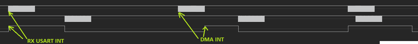
The nocomms signals is issued both in the RX USART interrupt and DMA end of transfer interrupt. The former isn't really needed as it is only fired if the DMA starts fetching USART bytes after the second received byte. Before checking the nocomms signal state, the AUX MCU takes into account the DMA interrupt latency.
As some MAIN to AUX command messages may require a little processing from the aux, every message from the main to the aux requires an answer (protocol flow control). For other messages, the aux MCU keeps dedicated buffers to do packet deserialisation. Every time the aux MCU receives a packet received interrupt (from the DMA controller), it therefore copies the received packet into the appropriate communication buffer.