MidiAddon - mist-devel/mist-board GitHub Wiki
Overview
The MIDI expansion board board adds a physical Atari ST compatible MIDI port to the MIST board.
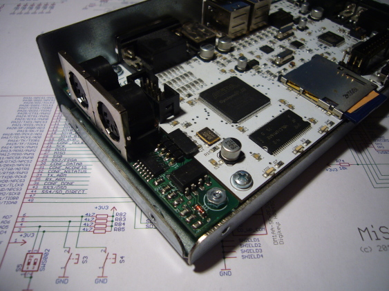
The MIDI expansion board connected to a series V1.2 MIST board.
Schematic
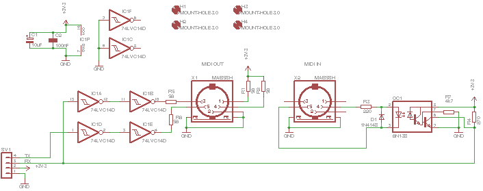
The board implements a simple MIDI compliant current loop. The MIST runs at 3.3V unlike the orifinal Atari ST which ran on 5V. The values of resistors R1, R2, R5 and R6 reflect this as well as the fact that IC1 is a low voltagle variant.
The MIDI expansion board implements MIDI through exactly like the original Atari ST did on Pin 1 and 3 of the MIDI out connector.
The board connects directly via SV2 to the FPGA expansion connector of the MIST board V1.2 or V1.3.
Printed Circuit Board
The board fits exactly at the left side of a MIST V1.2 or V1.3 (the first series board) board. Previous development boards may also be connected but need some extra wires.
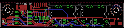
The resulting board looks like this:
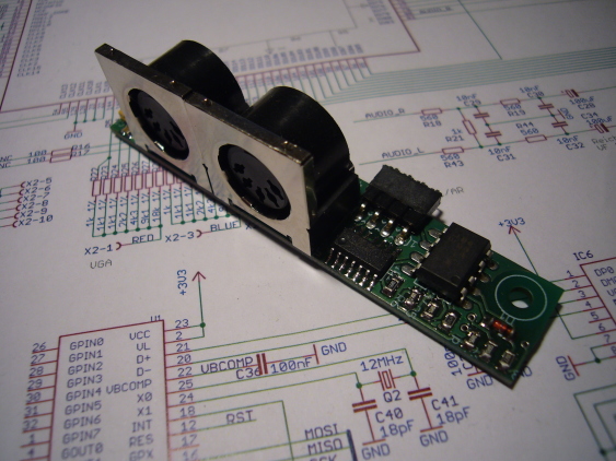
Case mounting
Mounting the MIDI expansion board in the case your MIST came in requires some minor metal work. First you need to drill two holes in the bottom part to mount the expansion board left of the MISTs mainboard using stand-offs. You can seethis in the picture above. You might also need to shorten the left screw securing the white front panel as it may collide with one of the stand-offs.
Then you need to drill two big holes in the left side of the top case so the MIDI plugs fit nicely and deep enough into the case to make secure contact.
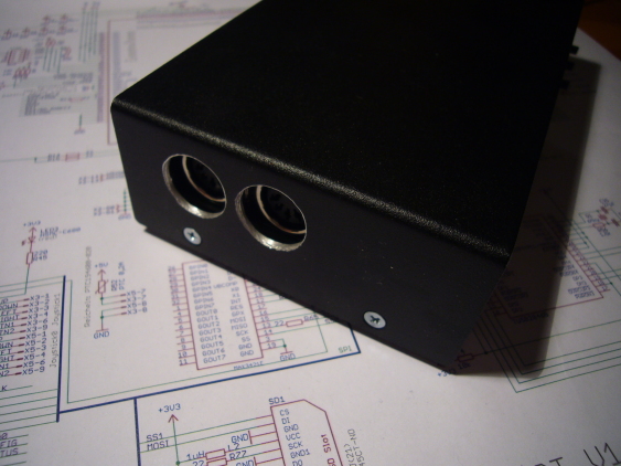
The resulting setup is very small yet robust.
Electrical considerations
MIDI was designed when 5V was the voltage being used in computers. Today it's 3.3V and less what most computers use internally. MIDI implementations struggle with this.
If we have a look at the schematic on this page you'll see the resistors R1 and R5 each being 56 ohms and both limiting the current that flows over pins 1 and 3 on connector X1 (MIDI OUT). That's where the board drives external gear.
The Atari ST was a 5V device and according to http://dev-docs.atariforge.org/files/520ST_Schematic.pdf used 220 Ohms in the same place (R77 and R80).
On the receiving side there's always a 220 ohms resistor (R3 on the MIST and R76 in the Atari ST)
This limits the current to 5V/3*220ohms = 7.5mA in short circuit or 5mA if the opto couplers LED on the receiver side drops 1.7V as (5V-1.7V)/3*220ohms = 5mA. This is what the MIDI standard assumes.
A diode with a voltage drop of 1.7V is driven by the MIST with (3.3V-1.7V)/(2*56 + 220) = 4.8mA. This is a difference of 0.2mA and is actually pretty close and should work. But what if your device has a LED with e.g. 2V voltage drop? Then you have 4.5mA with the 5V circuit and 3.9mA on the 3.3V cicruit. The difference is now 0.6mA. So the influence of the voltage drop of receiver LED becomes bigger in the 3.3V circuit.
It is possible to lower the values of R1 and R5 on a MiSTs MIDI add-on board. It's possible to add 100ohms on top of R1 and R3. This will effectively lower both resistors to 35 ohms and increase the current to (3.3-1.7)/(2*35 +220) = 5.5mA with a 1.7V LED or (3.3-2)/(2*35+220)=4.5mA with a 2V LED.
The additional current shouldn't hurt any device and may help those of your devices that have difficulties with the MIST. It also doesn't hurt the MiST. It can drive that current (a complete MiST draws about 300-400mA). But be aware that this exceed the MIDI specifications!
Core support
The Atari ST core supports the MIDI expansion board out of the box. And so does the latest Minimig AGA core as seen in the videos below.
Youtube videos
Supported/tested software
The Atari ST core has been tested against a PC running a MIDI synthesizer. Also a MIDIMAZE2 session has successfully been initiated between two boards. Here's a youtube video.