How to make wifi based version (Esp8266) - michalmonday/supremeDuck GitHub Wiki
If you'd like to create a better looking version you could check the documentation of Esp-12F based board I designed. It includes all essential resources needed to build it yourself but requires more equipment and effort than this version.
1. Get/assemble the hardware.
Previously the hardware was the same as in spacehuhn's wifi_ducky (as shown in the Seytonic's video). Currently I suggest to use slightly different setup (with an additional switch and different wiring) to make installation/updating easier.
Different boards/modules can be used for it, but the hardware must have:
A board with Atmega32U4 such as:
- Arduino Pro Micro 5V (with external 3.3V regulator or two 3.6V zener diodes)
- Arduino Pro Micro 3.3V (requires Sparkfun plugin)
- CJMCU Beetle (with external 3.3V regulator or two 3.6V zener diodes)
- SS Micro
- Arduino Leonardo (with external 3.3V regulator or two 3.6V zener diodes)
- Malduino Lite (with external 3.3V regulator or two 3.6V zener diodes)
- Malduino Elite
A board with Esp8266 module such as:
- Esp8266 12-F
- NodeMCU (most of the steps listed below are not applying to it because it can be flashed much more easily, all you have to do with is to upload Esp8266.ino to it using Arduino IDE, there are many guides on how to do that)
- Wemos D1 Mini (also can be programmed directly through its micro USB socket)
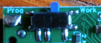
Additionally a switch is required, for example:
From my experience it is much better to use thin 30AWG wires instead of the less flexible and more problematic 22AWG wires like these.
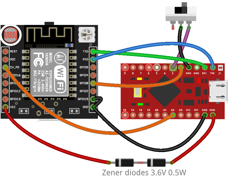
If the Atmega32u4 board operates on 5V (instead of 3.3V) then a voltage step-down module or 2x 3.6V 0.5W Zener diodes are required. The wiring image below shows how the wiring should look like using 2 Zener diodes.
2. Open the supremeDuck.ino code in Arduino IDE (make sure to download the whole folder, I suggest to download/clone the whole repository), uncomment line shown below and upload the code.
The line to uncomment is located in Definitions.h file and looks like this:
//#define WIFI_DUCKY_SETUP
It should look like this after uncommenting:
#define WIFI_DUCKY_SETUP
Select Tools -> Board -> Arduino Leonardo (for Atmega32u4 boards that operate on 5V, e.g. Esp12F based boards)
(If the board operates on 3.3V then use setting from Sparkfun plugin or Malduino plugin, both will allow to pick 3.3V version).
3. Download Esp8266Flasher program (32-bit, 64-bit).
The code uploaded in step 2 will make sure that the Esp8266 code uploaded using this program will reach Esp8266 even that it's not directly connected to PC (it's connected through the board with Atmega32U4).
4. Flip the switch to create connection between A2 and GND (switch would have to be flipped to the left on the wiring image above) and plug the device to PC.
This will tell Atmega32u4 to pass all the data from USB to the Esp8266, it will allow Esp8266 to be programmed. After plugging-in it should blink 3 times (just to let you know that it entered this mode).
5. Open the Esp8266Flasher program, load this bin file and flash it.
Pick the COM port corresponding to the connected device.
Press Config and click on the cog icon to load the file, check the corresponding checkbox and uncheck others. Use 0x00000 offset.
Press Advanced and select 115200 Baudrate, 4MByte Flash size, 80MHz Flash speed and DIO SPI Mode.
Press Operation and finally press Flash(F)
Note: The bin file was generated using Esp8266.ino file using
Arduino IDE -> Sketch -> Export compiled Binary, you could as well upload the Esp8266.ino file, however it would have to be uploaded directly to the wifi module, not through the Atmega32u4 (which is the advantage of using Esp8266Flasher program and bin file).
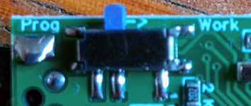
6. Plug-out the device, flip the switch and plug it back in.
The device should be in working order now. You could check this video to see how to use it instead of the initial bluetooth version. Please let me know on discord (michalmonday#3687) if you encounter any problems while following this guide.