433MHz Transmitter Receiver - mhightower83/Arduino-ESP8266-misc GitHub Wiki
Super Heterodyne 433MHz RF Receiver Modules marketed as RXB6 appear in a few forms. Some have an LDO regulator installed at U3 and some do not. My guess is the older ones with a chip at U3 are using the ~MICRF219A which is a 3.0 to 3.6V part. These need an LDO regulator to handle the up to 5.5V range. Those without an IC at U3 often have a ferrite SMD or resistor to bypass the LDO regulator, they are still using the old PCB layout. The unit I have is like this and it uses the SYN500R for the RF Receiver chip. When shopping online you cannot trust the pictures. Many show an IC at U3. Mine did; however, the device I received does not have the IC. Also, most of the photos I have seen have the 0Ω resistor R6 installed. This connects pin DER to DATA.
| Pin | Label | Function/Description |
|---|---|---|
| 1 | ANT | Antenna, connect 17.3cm wire for 433MHz. |
| 2 | GND | Optional Antenna Ground - ground plane 10 to 20 cm heavy foil or leave not connected. |
| 3 | GND | Power Ground |
| 4 | +5V | Vcc 5V, 3.0V - 5.5V DC power Also, connect a 10.0µF and 0.1µF capacitor to the ground. This pin feeds a ferrite bead (0.2Ω DC) which passes power under the tin. The traces show an option for a regulator IC. Some photos show a chip that most boards don't ship with. |
| 5 | +5V | Vcc 5V, 3.0V - 5.5V DC power This pin stretches over to the RF side of the board connecting to pin 4. |
| 6 | DER | D - receive Data, E - power Enable, R - RSSI - The function performed depends on the build or production run. The 0Ω resistor at R6, R5, or R7 determines the function of this pin. |
| This pin is DATA if R6 is a 0Ω resistor which makes a connection to pin 7. | ||
| This pin is power Enable if R5 is a 0Ω resistor. To disable you must pull to a logic 1. From datasheet for SYN500R "SHDN - Shutdown logic control input. Active internal pull-up." The module circuit under the metal lid supplements the SHDN pin with a 0.85µF capacitor to Vcc and a 75KΩ resistor to the ground. For a 75KΩ resistor to counter the "Active internal pull-up" the internal pull-up must be really weak. |
||
| This pin is an analog RSSI voltage indicator if R7 is a 0Ω resistor. Output is 0.4 to 2V from a buffer with 200Ω typical output impedance Output Current 400µA typical. RSSI response slope from -109dBm to -40dBm at 25 mV/dB. Move 0Ω resistor at R6 to R7 to convert DER pin from (default) Data to RSSI. |
||
| 7 | DATA | Receive Data pin. This pin has a drive capability of 0.4mA. |
| 8 | GND | Optional, return ground for Data pin. |
- RBX6 Module datasheet
-
SYN500R datasheet - My module has this one. The pinout looks the same as the MICRF219; however, this part accepts a 3.0V - 5.5V Vcc operating range. Thus no need for an LDO regulator. This explains U3 being replaced by a ferrite.
- My board is configured with:
- SEL0 Open, SEL1 Short - DEMOD BW 3250Hz, Shortest Pulse 200µs, Maximum data rate with 50% Duty Cycle 2500bps
- CAGC = 3.6µF, CTH = 0.43µF this set of values does not match the datasheet table's for SEL0 and SEL1.
- My board is configured with:
- MICRF219A - datasheet similar pinout - but different
- RSSI info / provide signal strength - looks like they are struggling to get RSSI working. (it didn't work for me either)
- RFLINK project - Some other info on "Receivers and Transmitters"
ID: 1629262, Bought it from banggood was real cheap.
This block is mostly the seller's product description with minor additions.
The kit includes one pair of transmitter and receiver modules and one pair of spring antennas for increasing the communication distance. And the frequency is 433MHz. It is very popular for remote control systems, such as Remote control rolling gates, smart cars, smart home, etc.
- Compatible with Arduino;
- Library: RadioHead, Sparkfun VirtualWire,
- Operating voltage: 3.5~12V DC;
- Working frequency: 433MHz;
- Transfer rate: 4KB/S (max);
- Transmission distance: 3 m (maximum) at VCC = 5V without additional antenna. When the spring antennas are soldered to the transmitter and receiver module, the transmission distance can be increased to 5 meters. The supply voltage is larger, the transmission distance farther.
- Compatible with Arduino;
- Library: RadioHead, Sparkfun VirtualWire,
- Operating voltage: 4.75~5.25V DC;
- Working frequency: 433MHz;
- Quiescent Current: 4mA;
- Great for DIY project.
1 x 433MHz RF transmitter module
1 x 433MHz RF receiver module
2 x 433MHz spring antenna (2.7cm)
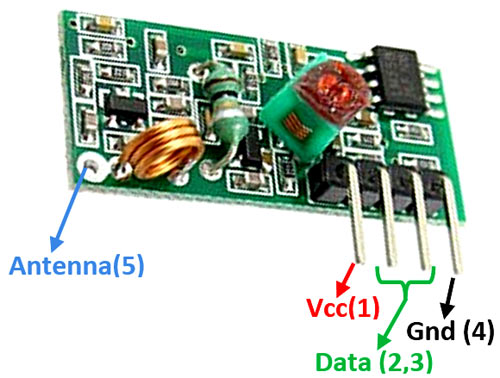
| Pin | Label | Function/Description |
|---|---|---|
| 1 | VCC | Vcc 5V, supply 4.75~5.25V DC power. Also, connect a 10.0µF and 0.1µF capacitor to the ground. |
| 2 | DATA | Receive Data pin. Bridged to pin 3 |
| 3 | DATA | Receive Data pin. |
| 4 | GND | Ground |
| 5 | Antenna, connect 17.3cm wire for 433MHz. |
- Using Inexpensive 433 MHz RF Modules with Arduino - This looks close
- Communicating with 433MHz OOK/ASK wireless modules (#88)
- Oregon Scientific RF Protocol Description MAY 2016 adds Ambient Weather
-
Arduino Oregon Library - Uses interrupts and supports THGR228N
- above author now uses RFLink - low value link - freeware project no sources that I can see
- Oregon_NR - Arduino ESP8266 Library in Russian, seems to work for my devices
- Oregon Scientific sensor logger
- rtl_433 via RTL-SDR, oregon_scientific.c
- Instructable RF433 Analyser - Interesting project and modifications to RXB6
While idle, the RF Receiver's AGC will go wide open. Equivalent to the volume being raised to full. All you would hear is noise, static. During this period you cannot have interrupts enabled. Most MCU would be overwhelmed and most likely crash. A better solution is to set an interrupt timer ISR, that samples the data pin, looking for the ones and zeros timings for a preamble. The duration of the preamble provides time for the AGC circuit to lock in the threshold for detecting ones and zeros. Conveniently at the conclusion of the transmission, this new threshold will create an extended gap, a period of silence. During the silence, the AGC drifts back to being wide open and static returns.
Once a clean preamble is detected, the preamble detection ISR is stopped. And an ISR that buffers data pin transition timing information is started. Once a frame of data has been detected, the ISR is shutdown and we go back to using the preamble detection ISR to sample the data pin.