mesoSPIM_scanlab_hardware_driver - mesoSPIM/mesoSPIM-hardware-documentation GitHub Wiki
Preparing the mesoSPIM ScanLab galvo system
- Preparing the mesoSPIM ScanLab galvo system
- Overview Scanlab Galvo System
- Scanlab Driver Boxes
- Necessary parts and tools
- Mechanical
- [drawing file folder: enclosure drawings]
- Bottom Alu plate
- enclosure
- Driver Electronics
- Elektronic PCB
- [drawing file folder: enclosure drawings]
- Necessary parts and tools
- Driver front panel
- Driver Electronics cable
- Elektronic PCB
- Scanlab Galvo mount
- Scanlab Power supply (thorlabs GPS011)
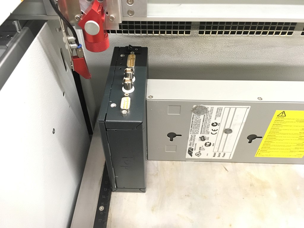
Overview Scanlab Galvo System

Scanlab Driver Boxes
Necessary parts and tools
- Enclosure Schroff product number 14820-133
- TBD xls list
Mechanical
drawing file folder: enclosure drawings
Bottom Alu plate
Needed for better stand and heatsink.
Bottom Alu plate, 150 x 60 x 4mm, 3 x M3 thread, 2x 3mm holes for flat head screw

enclosure
ToDo: drilling and milling the schroff metal enclosure; leftside, frontside, rightside, backside, bottom.
enclosure: tesa tape for closing enclosure holes for better air cirulation

left Driver enclosure Plate: mechanical modifiction of leftside
Lasercutter Trotec for engraving front (Z Hight)

Lasercutter Trotec for engraving front, placing inside
enclosure: clean engraving with Kontakt 60 spray

roughening enclosure Back plate

heat sink compound applied to heat sink and driver electronic
heat sink compound applied to enclosure back plate

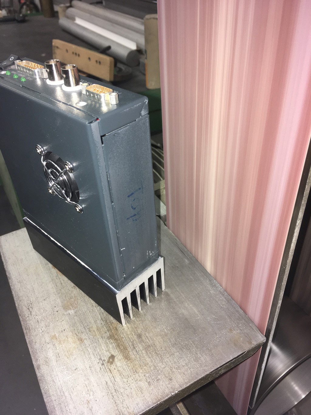
heat sink compound mounting; heat sink on bottom, then enclosure back plate, then driver electronic

enclosure: after grinding bottom side for better heat conduction
Driver enclosure bottom view, distance helpers

Driver enclosure bottom view, heat sink compound before mounting stand-plate

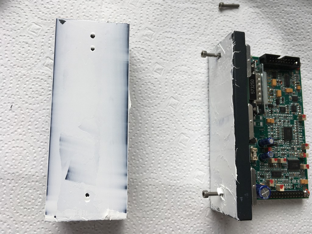
Driver Electronics
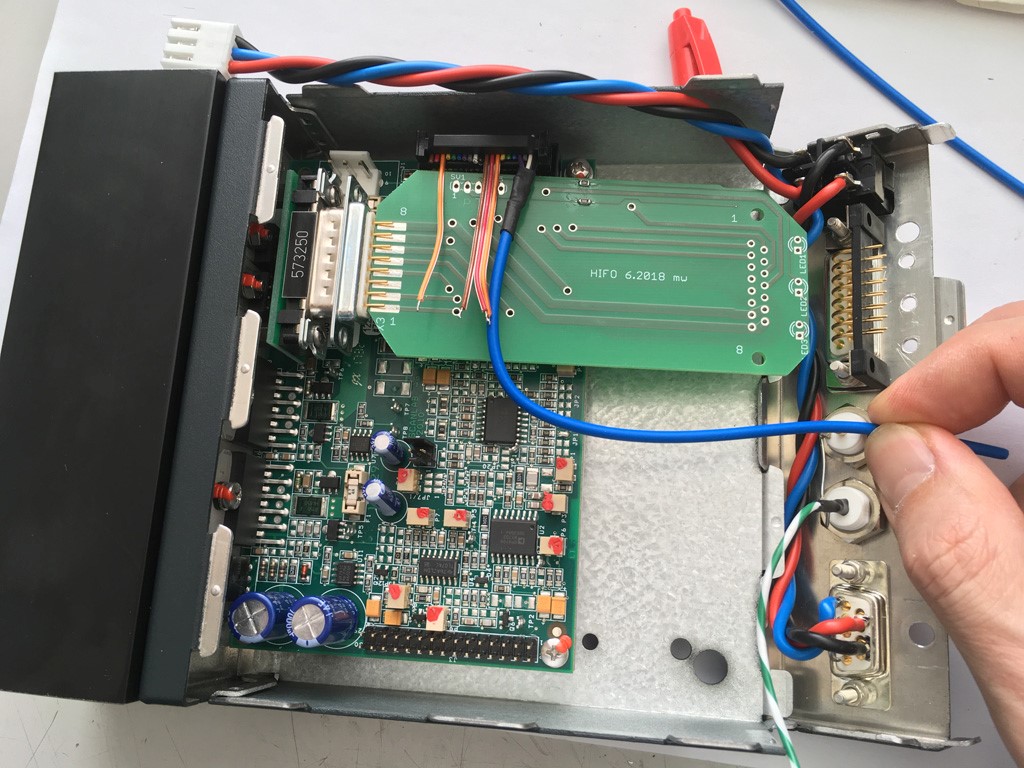
Inside Box, all done

Elektronic PCB
Version _4 is from 6.2008, first Batch. Version _v5 is the modified and untested version after first batch middle 2019.
Order Info: Leiterplatte: D-sub-verlaengerung-Scanlab Kunde: 44007 Format: Cadsoft Eagle 5.9 Ausführung: 2 - Lagen - Durchkontaktiert Format: 97,47mm x 43,50mm = 0,42dm² Material: FR4 1.55mm 70μm Cu Oberfläche: HAL bleifrei Min. Leiterbahnbreite: 200μm Min. Bohrdurchmesser: 0.2mm Lötstopplack: Top + Bottom, grün Positionsdruck: Top, weiss E-Test: Ja 10 pieces = Euro 106 + 19 shipping
Shipping time 7-10 days.
drawing file folder: enclosure drawings
Necessary parts and tools
tbd
Driver front panel
front panel overview

Adaptor-print connector; pin cable length

Adaptor-print connector; showing pin 1
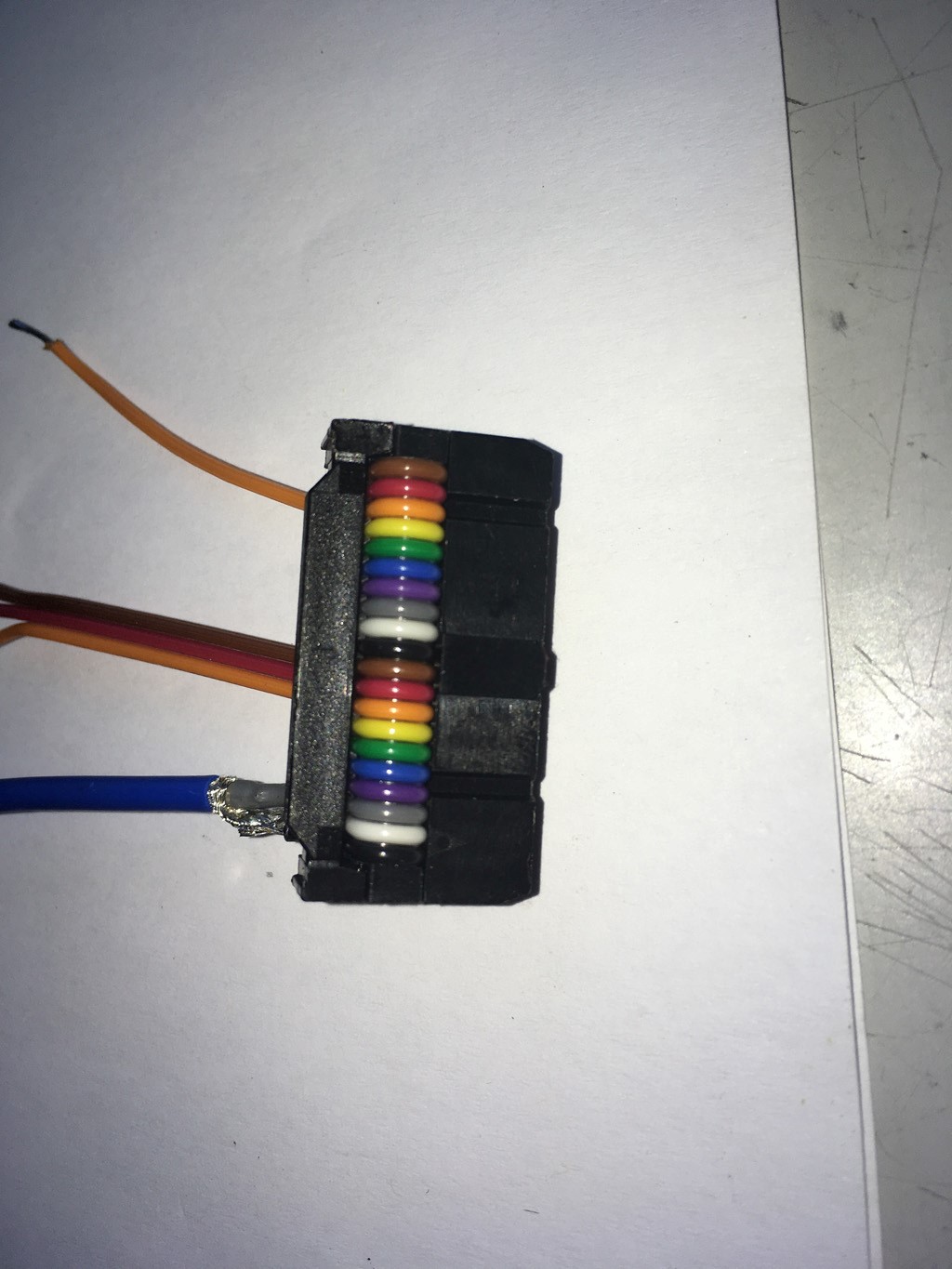
Adaptor-print connector; pin cable length 2

Driver; pin-header-plug to adaptor-print 1
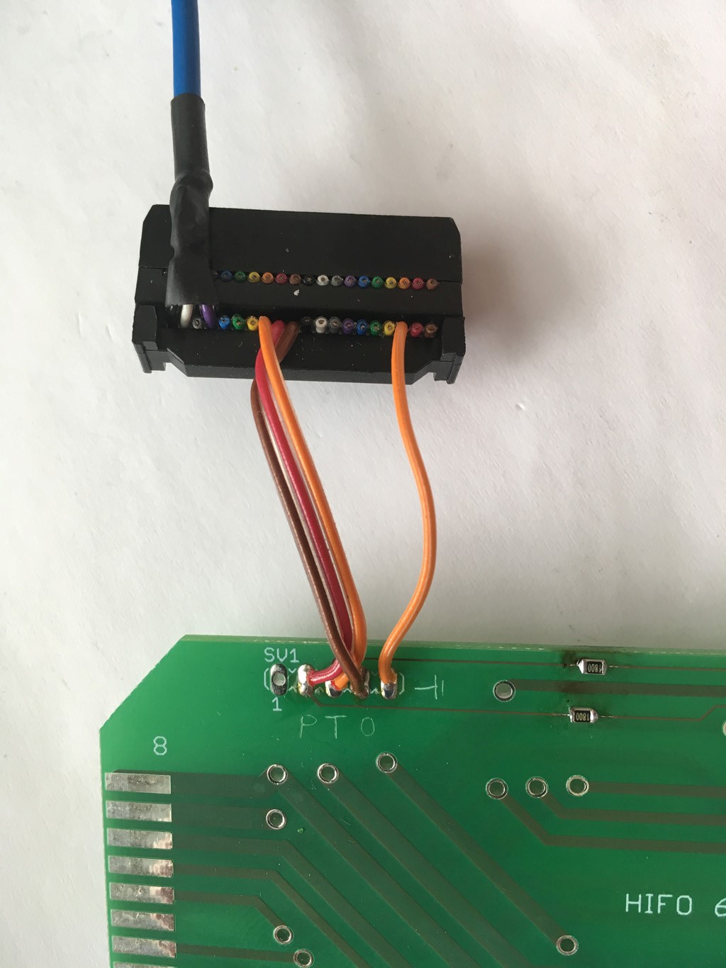
Driver; pin-header-plug to adaptor-print 2
 connector: driver to adaptor plate

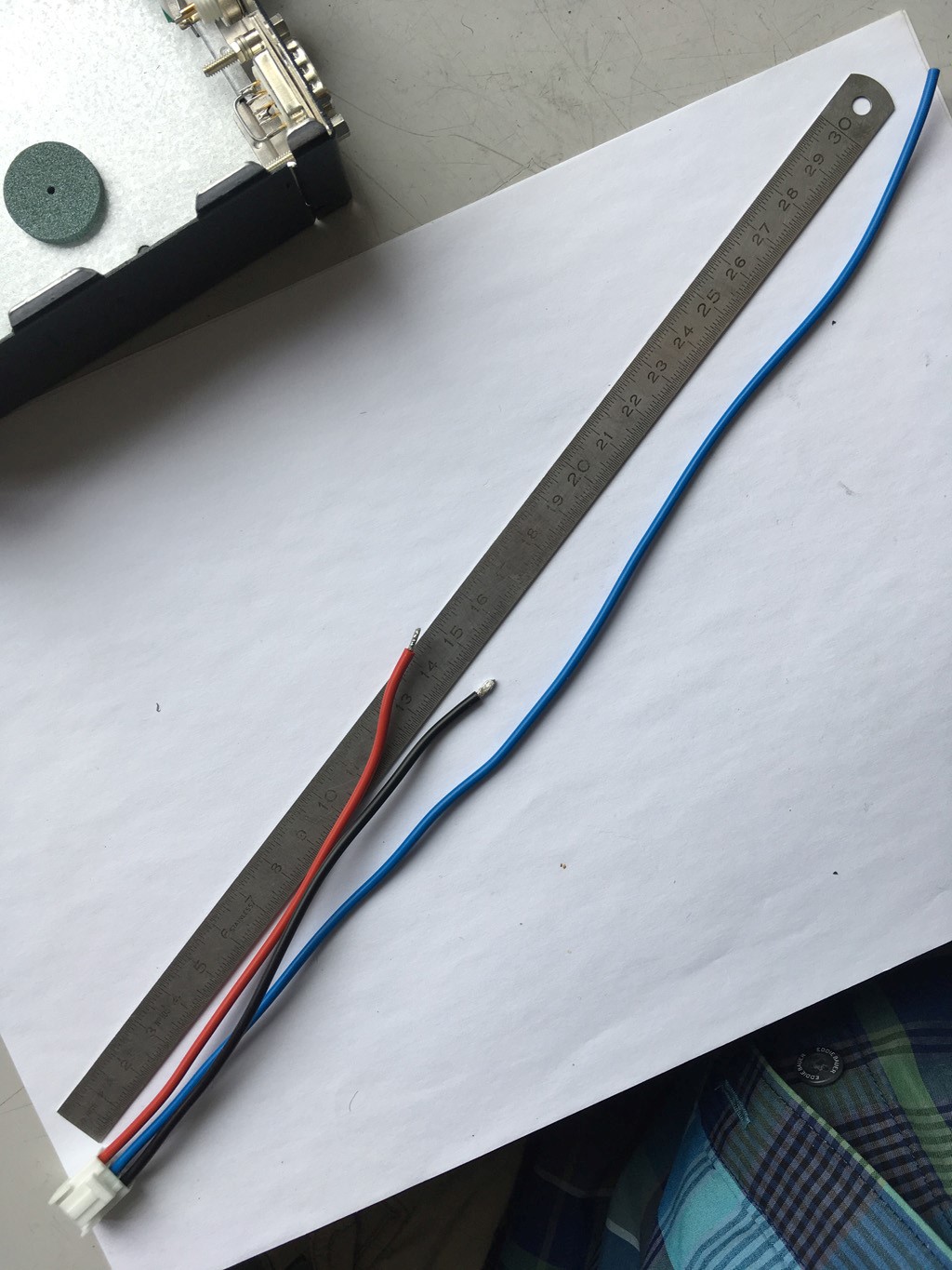
Adaptor-print connector; coaxial cable length

Driver; Driver-electronic, coaxial cable length
connector: BNC Position In to RG-147 coax cable

probe connector plug for Pos out , crimpsocket molex?? (or you solder it directly but not recommend)

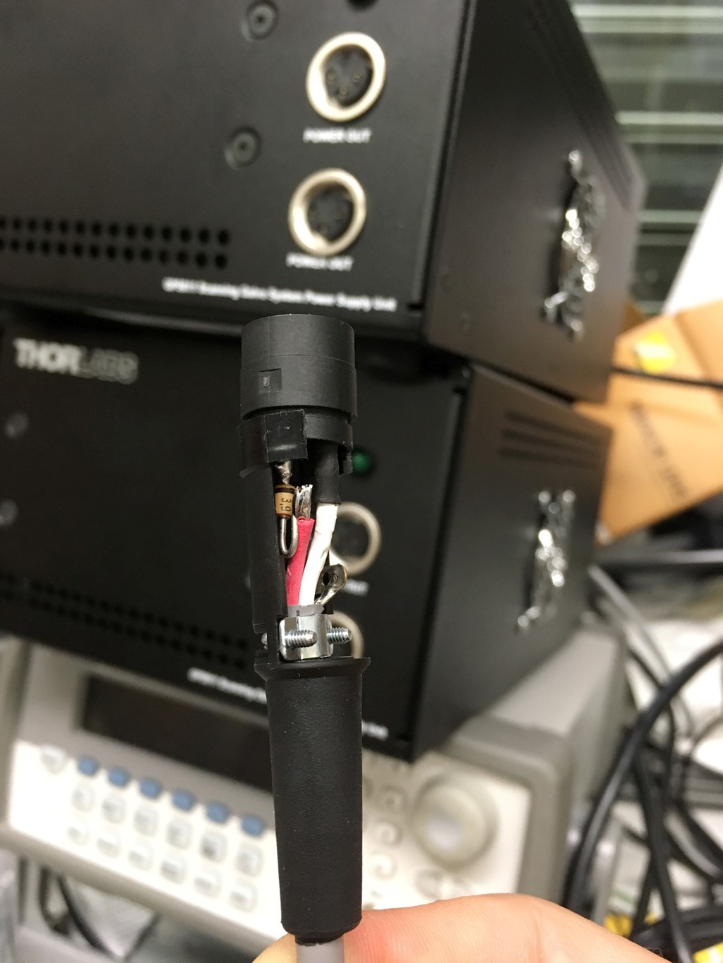
Driver; Driver-electronic powerplug to cable
Driver; power socket details

Driver; Driver-electronic powerplug to cable to power-switch on front

Driver; Driver-electronic powerplug to cable to power-switch on front 2

Driver; Driver-electronic powerplug to cable to power-switch on front and Pos out probe connector plug

important! place the adaptor-print exactly between the two DB15, close the enclosure, and then begin to solder the DB15 connectors
Driver; adaptor-print, solder via's, Top

Driver; adaptor-print, solder via's, Bottom

Driver; adaptor-print, solder front DB15
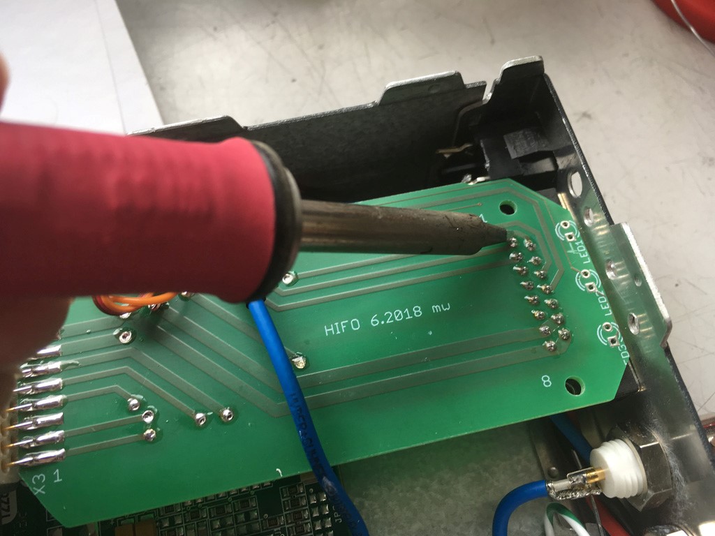
Driver; adaptor-print, solder LED's

adaptor print: Led's soldered (botton pin is ground)

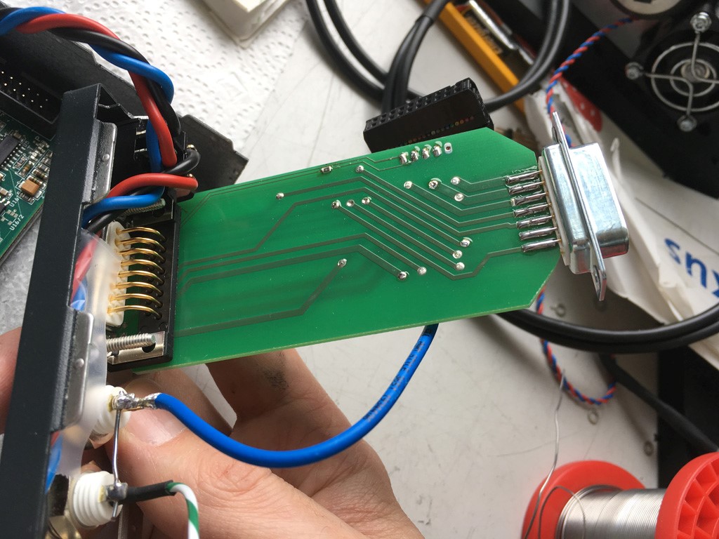
adaptor print: both Dsub soldered

adaptor print: back side
Driver fan; cable length, resistor, pin header

Do not forget to mount the Finger-Guard
Driver Electronics cable
Driver; prepairing Power cable from thorlabs

Driver; soldering power plug DB9 to thorlabs cable

Driver; thorlabs cable to DB9 power plug

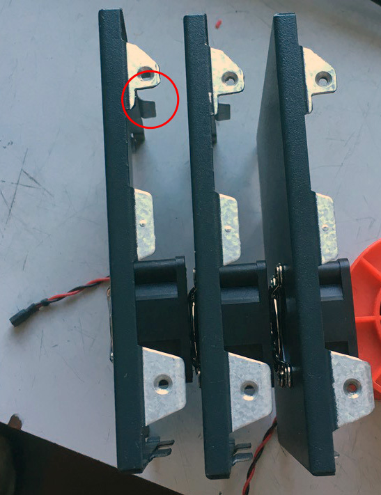
Scanlab Galvo mount
Necessary parts and tools
tbd
Galvo block and fan cooling aggregate with surface finish

Galvo block and fan cooling aggregate mount with heat conducting film

connector: Galvo plug, replacing clip with screws

modified power plug with 3.9V Z-Diode
Galvo fan; cable fan to cable thorlabs, soldering
 Ventilator mounting
 Galvo unit with mount, fan and cables

Scanlab Power supply (thorlabs GPS011)
Necessary parts and tools
tbd
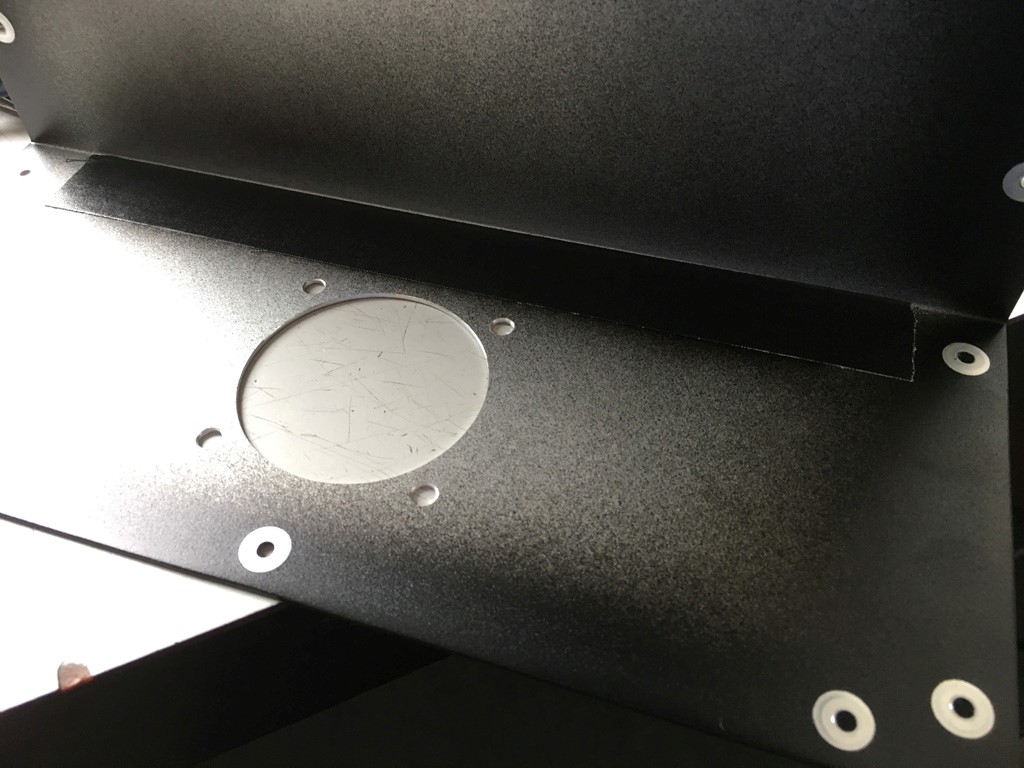
Position of Fan cutout and holes
 Fan cutout with 5mm verax fan screws
 Voltage reduction for Fan, Resistor prepairing
 Voltage reduction for Fan, Resistor soldering and covering
 Overview Fan modification
 Cables inside to band

Test
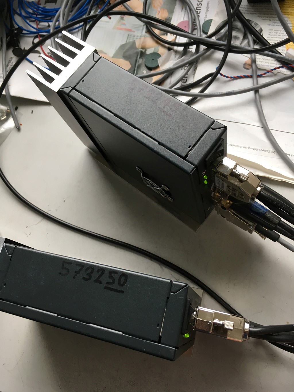
Drivers
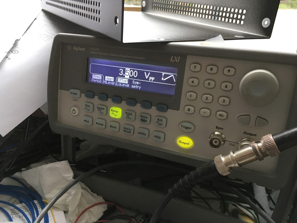
 Signal Generator, 200Hz, symmetry 50%, 3.500Vpp
 Oscilloscope, Position output
