mesoSPIM_excitation_path_galvo_rotation - mesoSPIM/mesoSPIM-hardware-documentation GitHub Wiki
Galvo rotation and scan lens installation
Setting up the scanner rotation
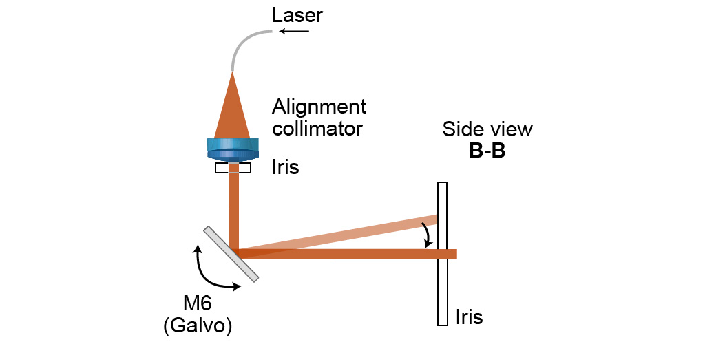
The scanner should be rotated in its mount so that the beam is on axis if 0V are applied. When doing this step, is important to check again and again that the scanner is truly at 0V. Often, galvo scanners will move to a non-zero position when switched off.
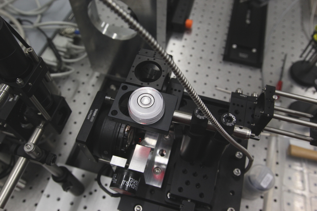
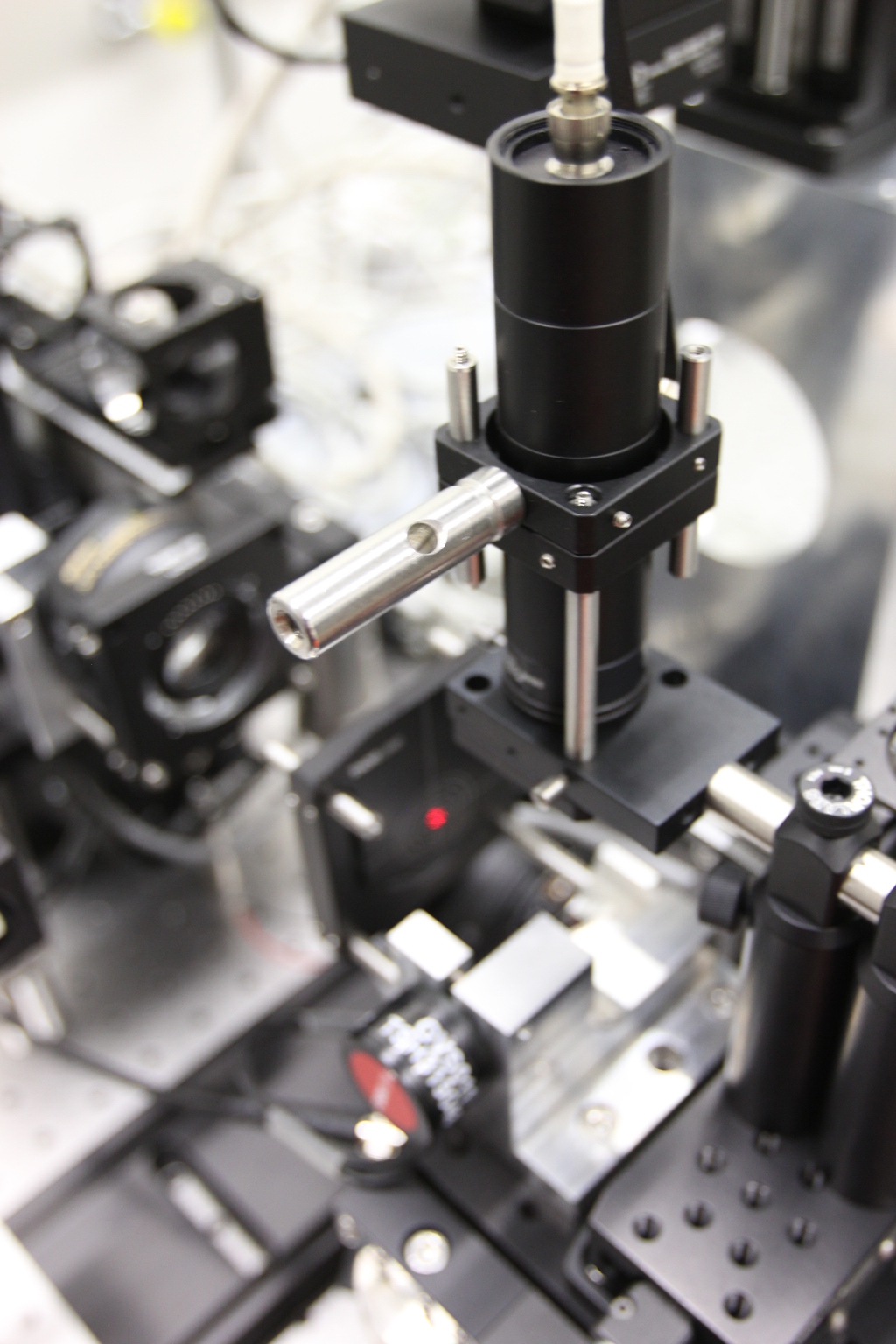
Leveling the holder 30 that will carry the alignment collimator / laser.
Connect the Galvo scanner to a source with 0V / short the input to GND:

Put the alignment collimator into the holder 30 and stop the beam down to <10 mm diameter using an adjustable iris. Make sure that the beam hits the scan mirror in the center using the manual linear stage.
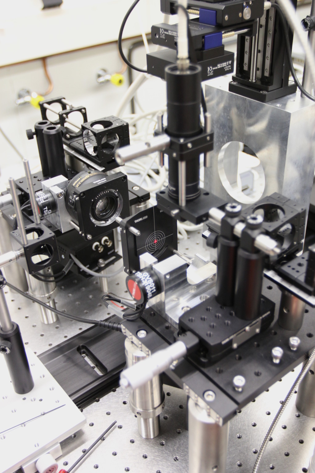
Attach a spare 60 mm cage plate and a few rods to be able to insert a 60 mm alignment target. Rotate the galvo scanner so that the beam is centered on the alignment target.
Depending on how you set up the system, do the same for the other excitation path:

Mount the Nikon excitation lenses in their 60 mm cage plates
Attach the cage plate to the scanner mount using two ER posts (each composed of an ER2 and an ER05). The posts are secured to the scanner mount using set-screws.
Making the excitation lens mounts parallel to the main rail
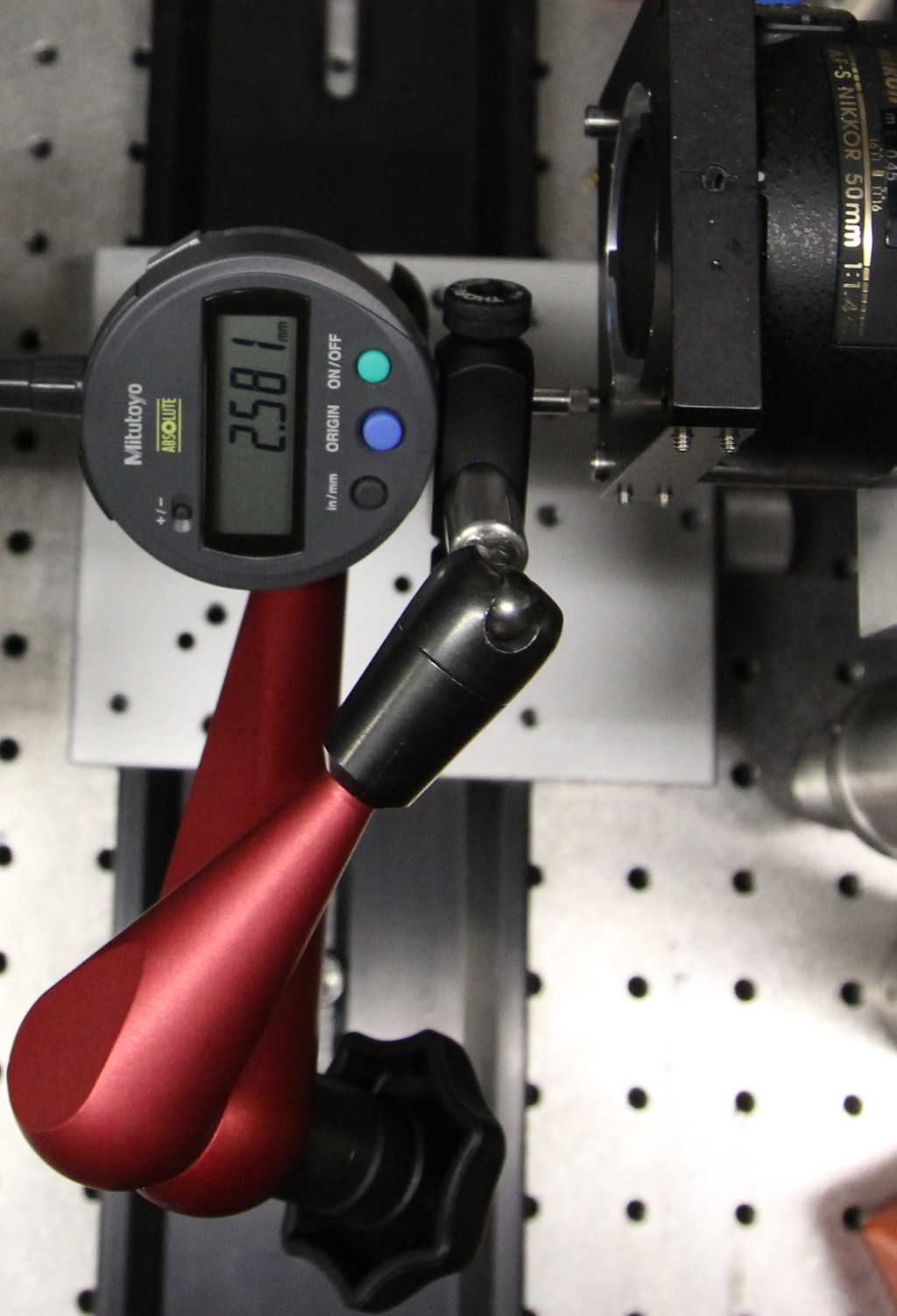
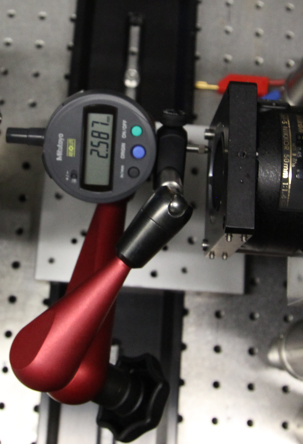 This is done using the digital indicator by indicating against the
surface of the cage plate. Here, there is only 0.007 mm difference across
the length of the cageplate - usually everything below 0.02 mm is ok.
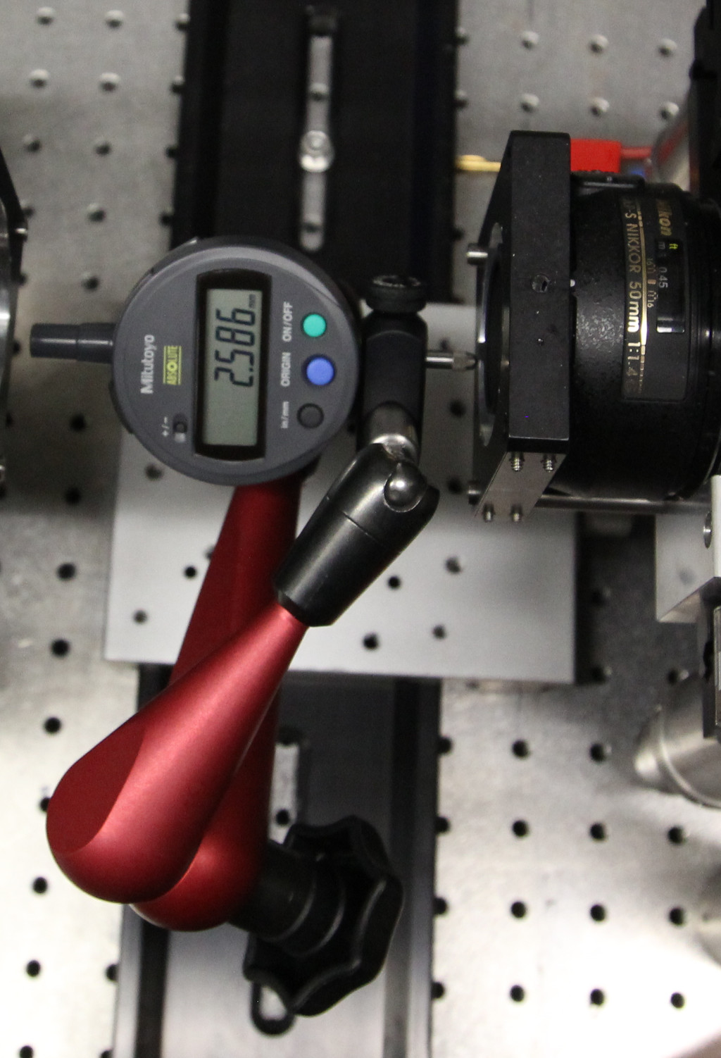
This is done using the digital indicator by indicating against the
surface of the cage plate. Here, there is only 0.007 mm difference across
the length of the cageplate - usually everything below 0.02 mm is ok.