IBM PC XT Keyboard Protocol - mcaple/tmk_keyboard GitHub Wiki
TMK Converter for XT keyboard
The goal is to emulate behaviour of IBM XT PC host interface comprised of logic ICs and to support virtually all of existent XT keyboards in the result. I hope so at least. You can get firmware and info from links below.
TMK IBMPC Converter
- https://github.com/tmk/tmk_keyboard/tree/master/converter/ibmpc_usb
- https://geekhack.org/index.php?topic=103648.0
TMK XT Converter
- https://github.com/tmk/tmk_keyboard/tree/master/converter/xt_usb
- https://geekhack.org/index.php?topic=94649.0
Protocol
Host or converter should read data line at falling edge of clock accroding to TechRef schematic and waveforms.
Host can hold data line low to inhibit keyboard from sending data.
XT keyboard signaling seems to exist two dialects; legitimate IBM XT with two start bits and Clones with one start bit.
1. IBM XT(two start bits)
IBM keyboard places 0 on first falling edge and 1 on second. The first start bit should be ignored or has no effect in XT host interface. Some of clones like Lynk also emulate this signaling.
Let's reffer to first one as pseudo start(0) and second as start(1) here.
We should read data line 10 times at falling egdes:
start(0), start(1), bit0, bit1, bit2, bit3, bit4, bit5, bit6, bit7
Note for start(0)
The start(0) bit has very tight time margin(around 5us) to read data line as Low because IBM XT Keyboard releases data line to Hi immediately after clock line falls without any wait. See waveform of IBM XT keyboard below.
The start(0) happens with just two machine instructions like below and the instructions take only two machine cycles of Intel 8048(2.5us/cycle) each.
0245: 98 BF   ANL BUS,#$BF     ; ok, CLK high: pull it low
0247: 88 20   ORL BUS,#$20     ; and release DATA..
That 5us may not be enough margin even for modern microcontroller and it can misses the bit without special care. What we can do is to read as fast as possible after the first clock. With AVR with 16MHz ISR elaborately defined with C takes a few micro seconds(aroudn 3us) and ISR_NAEKED with simple assembly code require 700ns.
2. Clones(one start bit)
They have just one start bit on first falling edge and their clock is fast in comparison with original.
Reading at falling edges:
start(1), bit0, bit1, bit2, bit3, bit4, bit5, bit6, bit7
Idea on How to discriminate IBM XT and Clones
We can know it by checking clock and data line while in idle state on startup?
1. IBM XT: clock:Hi, data:low
2. Clones: clock:Hi, data:Hi
This may be useful in case that it is hard to read start(0) correctly.
References
IBM XT Technical Referenc March 1986
This is protocol description for Enhanced 101/102-key keyboard.
Clock and Data Signals
The keyboard and system communicate over the 'clock' and
'data' lines. The source of each of these lines is an
open-collector device on the keyboard that allows either the
keyboard or the system to force a line to an inactive (low) level.
When no communication is occurring, the 'clock' line is at an
active (high) level. The state of the' data' line is held inactive
(low) by the keyboard.

An inactive signal will have a value of at least 0, but not greater
than +0.7 volts. A signal at the inactive level is a logical O. An
active signal will have a value of at least +2.4, but not greater
than +5.5 volts. A signal at the active level is a logical 1.
Voltages are measured between a signal source and the dc
network ground.

The keyboard 'clock' line provides the clocking signals used to
clock serial data from the keyboard. If the host system forces the
'clock' line to an inactive level, keyboard transmission is inhibited.

When the keyboard sends data to the system, it generates the
'clock' signal to time the data. The system can prevent the
keyboard from sending data by forcing the 'clock' line to an
inactive level, or by holding the 'data' line at an inactive level.

During the BAT, the keyboard allows the 'clock' and 'data' lines
to go to an active level.

Data Stream
Data transmissions from the keyboard consist of a 9-bit data
stream sent serially over the' data' line. A logical 1 is sent at an
active (high) level. The following table shows the functions of
the bits.
Bit 	 Function
1 Start bit (always 1)
2 Data bit 0 (least-significant)
3 Data bit 1
4 Data bit 2
5 Data bit 3
6 Data bit 4
7 Data bit 5
8 Data bit 6
9 Data bit 7 (most-significant)

Keyboard Data Output
When the keyboard is ready to send data, it first checks the status
of the keyboard 'clock' line. If the line is active (high), the
keyboard issues a request-to-send (RTS) by making the 'clock'
line inactive (low). The system must respond with a clear-to-send
(CTS), generated by allowing the 'data' line to become active,
within 250 microseconds after RTS, or data will be stored in the
keyboard buffer. After receiving CTS, the keyboard begins
sending the 9 serial bits. The leading edge of the first clock pulse
will follow CTS by 60 to 120 microseconds. During each clock
cycle, the keyboard clock is active for 25 to 50 microseconds.
Each data bit is valid from 2.5 microseconds before the leading
edge until 2.5 microseconds after the trailing edge of each
keyboard clock cycle.
http://www.minuszerodegrees.net/manuals/IBM_5155_5160_Technical_Reference_6280089_MAR86.pdf 4-33
Industrial Computer Technical Reference
When the keyboard is ready to send data, it first checks the status of the keyboard 'clock' line. If the line is active (high), the keyboard issues a request-to-send (RTS) by making the 'clock' line inactive (low). The system must respond with a clear-to-send (CTS), generated by allowing the 'data' line to become active, within 250 microseconds after RTS, or data will be stored in the keyboard buffer. After receiving CTS, the keyboard begins sending the 9 serial bits. The leading edge of the first clock pulse will follow CTS by 60 to 120 microseconds. During each clock cycle, the keyboard clock is active for 25 to 50 microseconds. Each data bit is valid from 2.5 microseconds before the leading edge until 2.5 microseconds after the trailing edge of each keyboard clock cycle.
Explanation of XT keyboard 8048 code
Very detailed commentary for XT keybaord
http://www.halicery.com/Hardware/Intel%208042%20and%208048/8048_XT_INTERN.TEXT
Comments of AT2XT keyboard converter
Quoted from useful comment of AT2XT keyboard converter. https://gist.github.com/tmk/5604a84f40cefeb5b359a114634db221#file-xtatkey-asm-L466-L479
;	The XT interface is very simple.  Bits are shifted into an 74LS322 shift
;	register.  When the start bit reaches the high-order bit of the shift
;	register, it sets an interrupt, disables shifting and pulls data low one
;	shift time later.  In other words, the start bit is shifted out.
;	The bit order is LSB first for 8 data bits.  After that, the interface
;	is essentially blind until the PC has picked up the character.
;
;	Many keyboards start out by strobing a low "pseudo-start"  bit, then
;	follow with a high "real start".  Apparently, this results in more
;	stable performace.  We'll do the same thing.
;
;	At some point, the XT host will drop the keyboard clock
;	line for 20 mS or more.	 When this happens, we need to
;	simulate a keyboard reset.
BIOS holds Clock line Low for 20ms to issue keyboard soft reset. And Data line should be Hi probably. See keyboard soft reset.
;	Clock is held low by the PC as an inhibit--the keyboard should (and
;	cannot) send data until both data and clock lines have been allowed
;	to go high.
In XT protocol host can hold Data line low to inhibit keyboard to send data, not instead of Clock line.
IBM 7531/7532 Technical Reference
Mode 1 Output: When the keyboard is ready to send data, it first checks the status of the keyboard 'clock' line. If the line is active (high), the keyboard issues a request-to-send (RTS) by making the 'clock' line inactive (low). The system must respond with a clear-to-send (CTS), generated by allowing the 'data' line to become active, within 250 microseconds after RTS, or data will be stored in the keyboard buffer. After receiving CTS, the keyboard begins sending the 9 serial bits. The leading edge of the first clock pulse will follow CTS by 60 to 120 microseconds. During each clock cycle, the keyboard clock is active for 25 to 50 microseconds. Each data bit is valid from 2.5 microseconds before the leading edge until 2.5 microseconds after the trailing edge of each keyboard clock cycle.
Data line is actually pulled down by IBM XT keyboard in idle state and released immediately after Clock line is pulled down(CTS). If host already releases Clock line in idle RTS is not required in fact, this is the case for TMK and Soarers' converter.
Waveforms
IBM XT(Two start bits):
    ____       _ 1 _ 2 _ 3 _ 4 _ 5 _ 6 _ 7 _ 8 _ 9 _______
CLK     \_____/ \_/ \_/ \_/ \_/ \_/ \_/ \_/ \_/ \_/
             _____ ___ ___ ___ ___ ___ ___ ___ ___
DAT ________/     \___X___X___X___X___X___X___X___\_______
        ^   ^  S    0   1   2   3   4   5   6   7
        RTS CTS

XT Clones(One start bit):
    ____________ 1 _ 2 _ 3 _ 4 _ 5 _ 6 _ 7 _ 8 _ 9 _______
CLK             \_/ \_/ \_/ \_/ \_/ \_/ \_/ \_/ \_/
    ______________ ___ ___ ___ ___ ___ ___ ___ ___ _______
DAT               \___X___X___X___X___X___X___X___/
               S    0   1   2   3   4   5   6   7
Two start bits
IBM PC XT and Lynk 122 Key terminal(LX-122-US)

This shows "Q"(0x10).
https://geekhack.org/index.php?topic=62168.msg1469706#msg1469706
Another IBM PC XT
 https://geekhack.org/index.php?topic=17458.msg350637#msg350637
IBM PC XT - kbdbabel.org
 This diagram in kbdbabel.org refers to stop bit but XT protocol doesn't use stop bit as explained above.
Zhan XT keyboard
Key 'B'(0x30)
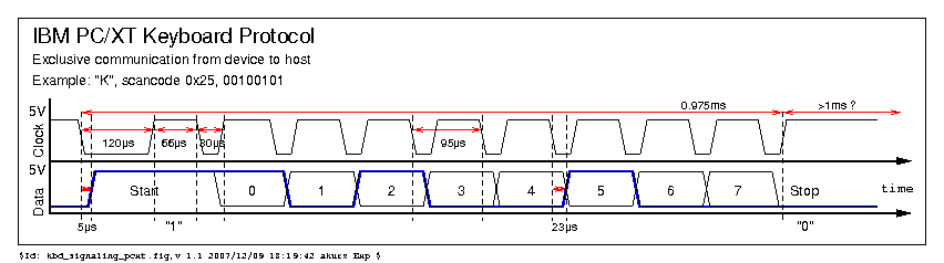
 Key 'K'(0x25)
 https://deskthority.net/viewtopic.php?p=467589#p467589
These are captures of XT and AT signal at Engicoder's XT to PS/2 converter.
XT input 'K'(0x25), AT output 'KP4'(0x6B)
 The converter reads 'K' 0x25(01 1010 0100) as 'KP4' 0x4B(1 1101 0010 0) incorrectly, then converts to AT 'KP4' 0x6B here.
XT input 'B'(0x30), no AT output
 The converter reads 'B' 0x30(01 0000 1100) as 0x61(1 1000 0110 0) incorrectly, then fails to convert probably.
https://deskthority.net/viewtopic.php?p=467824#p467824
XT Model F ?
These are captures of XT and AT signal at Engicoder's XT to PS/2 converter.
Note that data line of XT is HI at idle state unlike other IBM XT keyboards. The poster referred to this keyboard as just 'Model F XT'. This is not genuine IBM XT keyboard or different revsion, perhaps.
Key 'B'(XT:0x30, AT:0x32)
 Key 'K'(XT:0x25, AT:0x42)
 https://deskthority.net/viewtopic.php?p=467824#p467824
One start bit
Leading Edge DC-2014


This shows released "Z"(0xAC).
Zenith Z-150 XT(black label)

Microtech made in Brazil

This shows "A"(0x1E) on left and "S"(0x1F) on right.
- https://geekhack.org/index.php?topic=17458.msg2564783#msg2564783
- https://geekhack.org/index.php?topic=17458.msg2566372#msg2566372
Note that you have to read this signaling at falling edge legitimately while other clone keyboards can be read at rising edge also.
Monterey
https://geekhack.org/index.php?topic=17458.msg362823#msg362823
XT Keyboard Interface
Host side schematics
XT keyboard interface is defined just with 8-bit shift register and flip-flops TTL chips.
With the two flip-flops of LS175 clock line pulse from keyboard gets synchronized and inversed, the synchronized clock pulse is given to CLK pin of shift register(74LS322), in the result data is read at falling edge of clock line.
IRQ1 is trrigered by shifted-out start(1) bit on QH' pin once bit0 to bit7 are stored in shift register. Data line is kept low until BIOS gets data from the shift register and IRQ1 is cleared.
Holding clock line for 20ms means soft keyboard soft reset.

PCLK of 8284A(14.3181/6=2.386MHz or 420ns per cycle) is given to CLK pin of LS175, so it takes 840ns(2 cycles) to sample data line after falling edge of keyboard clock line?? Processor clock is 4.77MHz(14.3181/3).

https://en.wikipedia.org/wiki/Intel_8284

D-10, D-2: http://bitsavers.org/pdf/ibm/pc/xt/1502237_PC_XT_Technical_Reference_Apr83.pdf
Keyboard side schemaitcs

 D-12, D-14: http://www.bitsavers.org/pdf/ibm/pc/xt/1502237_PC_XT_Technical_Reference_Apr83.pdf
Assuming oscillator frequency is around 6MHz, machine cycle will be 2.5us(15/F). p13: https://archive.org/details/grokking-the-mcs-48
Colppit oscillator: 7.34MHz(47uH,20pF,20pF)? https://www.electronics-tutorials.ws/oscillator/colpitts.html
Max clock frequency of 8048/8049 is 6MHz or 11MHz for faster version. https://en.wikipedia.org/wiki/Intel_MCS-48#Variants
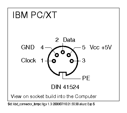
Connector
DIN 5P 180-degree

- http://kbdbabel.org/conn/kbd_connector_ibmpc.png
- https://allpinouts.org/pinouts/connectors/input_device/keyboard-xt-5-pin/
Pin 3 is used to reset keyboard for IBM PC/XT Type-1 and some clones. See this for details. https://github.com/tmk/tmk_keyboard/wiki/IBM-PC-XT-Keyboard-Protocol#keyboard-hard-reset
Pull up resistors
2K Ohm on keyboard and 4.7K on host.
Keyboard Hard Reset
On powering on XT host outputs reset signal to keyboard through KBDRESET Pin 3 of keyboard connector(D-10), which is controlled by reset output pin of 8284A clock oscillator(RESET on D-2, ~RESETDRV on D-3). The 8284A chips uses 'PowerGood' signal from power supply unit as original source of the reset signal. The reset output of the chip is also used to initializes 8086 processor and other chips on XT system.
Sorarer's converter emulates this with 500ms low pulse on PB7 pin for hard reset. Also TMK converter does same thing with PB7 and PB6(for Pro Micro support).
D-2,3,10: http://bitsavers.org/pdf/ibm/pc/xt/1502237_PC_XT_Technical_Reference_Apr83.pdf
8284A: https://en.wikipedia.org/wiki/Intel_8284
PowerGood: https://en.wikipedia.org/wiki/Power_supply_unit_(computer)#Original_IBM_PC,_XT_and_AT_standard
Type-1 vs Type-2
IBM PC XT keyboard Type-1 requires hard reset while Type-2 doesn't not conneted to the reset pin.
https://vintagecomputer.ca/ibm-pc-model-f-keyboard-type-1-vs-type-2/
Clones
Some of clones are also known to need the reset.
Zenith Z-150 XT: https://deskthority.net/viewtopic.php?f=2&t=12972&start=60#p425932
Leading Edge DC-2014: https://geekhack.org/index.php?topic=17458.msg1501460;topicseen#msg1501460
Chip datasheets
8048
https://www.ceibo.com/eng/datasheets/Intel-8048-Manual.pdf
LS175 D Flip-Flop
D inputs is stored during the LOW to HIGH clock transition.
http://www.uni-kl.de/elektronik-lager/417744
Two clock domains synchronization. Clock signal from keyboard and XT system internal clock.
https://www.eetimes.com/document.asp?doc_id=1276114
http://www-inst.eecs.berkeley.edu/~cs150/sp12/agenda/lec/lec16-synch.pdf
https://en.wikipedia.org/wiki/Metastability_(electronics)
74LS74 Positive-edge D Flip-Flop
http://www.ti.com/lit/ds/symlink/sn74ls74a.pdf
74LS322 8-bit Shift Register
https://www.unicornelectronics.com/ftp/Data%20Sheets/74ls322.pdf
SN75477 PERIPHERAL DRIVERS
http://www.ti.com/lit/ds/slrs025a/slrs025a.pdf
PB2(misslabeled PB3 on schematic of TechRef '84?) output of 8255A is connected to SN75477 through E5 jumper. It seems that PB2 signal is inverted by this chip and can control keyboard data line when enabling this connection by E5 but it is disabled by default. PB2 can be ignored??
PC XT BIOS code
- KB_INT: p5-50 of TechRef
- VECTOR TABLE: p5-102 of TechRef
- KBD_RESET: p5-98 of TechRef
- TechRef: http://bitsavers.org/pdf/ibm/pc/xt/6361459_PC_XT_Technical_Reference_Apr84.pdf
8255 Port p1-26
PORT_A: Output
        Keyboard Scan Code
PORT_B: Output
        PB0 + Timer 2 Gate Speaker
        PB1 + Speaker Data
        PB2 Spare
        PB3 Read High Switches Or Read Low Switches (PORT_C DIP SW read select p1-39)
        PB4 - Enable RAM Parity Check
        PB5 - Enable I/O Channel Check
        PB6 - Hold Keyboard Clock Low
        PB7 - (Enable Keyboard) Or + (Clear Keyboard) [clear shift register and keyboard IRQ] p1-39
PORT_C: Input
        PC0 Loop on POST (read DIP SW1/SW5 p1-39)
        PC1 + Co-Processor Installed (read DIP SW2/SW6)
        PC2 + Planar RAM Size 0 (read DIP SW3/SW7)
        PC3 + Planar RAM Size 1 (read DIP SW4/SW8)
        PC4 Spare
        PC5 + Timer Channel 2 Out
        PC6 + I/O Channel Check
        PC7 + RAM Parity Check
8088 IRQ1(interrupt 09h)
KB_INT routine is called on each IRQ1 and it clears IRQ1 and shift register by hi(1) pulse of PB7 on 8255A. Scan code 0xFF indicates overrun error and the routine just makes beep for that.(p5-50)
Keyboard soft reset
KBD_RESET resets keyboard with pulling clock line low for 20ms(p5-98), keyboard is expected to return 0xAA(p5-32).
And Data line should be Hi probably. Keyboard checks if Data line is Hi for a while. See around 0287-02BE. http://www.halicery.com/Hardware/Intel%208042%20and%208048/8048_XT_INTERN.TEXT
PORT_B, KB_CTL(61h)
Asserting PortB bit7(PB7) of 8255A clears shift register and IRQ1. PORTB bit6(PB6) of 8255A controls clock line, which is 1 normally.
PB2 data line control
This is misslabeled PB3 on schematic of TechRef '84. It seems that PB2 signal is inverted by SN75477 and can control keyboard data line when enabling this connection by E5 but it is disabled by default. PB2 should be ignored??
In p.45(1-26) of this reference PB2 is called as 'Spare'. http://bitsavers.org/pdf/ibm/pc/xt/6361459_PC_XT_Technical_Reference_Apr84.pdf
Scan Code Special Handling
P.2-16 of TechRef'83
System Reset
The combination of the Alt, Ctrl, and Del keys will result in the keyboard routine initiating the equivalent of a "system reset" or "reboot." System reset is handled internal to the keyboard.
Break
The combination of the Ctrl and Break(Scroll Lock) keys will result in the keyboard routine signaling interrupt hex lA. Also, the extended characters CAL = hex 00, AH = hex 00) will be returned.
Pause
The combination of the Ctrl and Num Lock keys will cause the keyboard interrupt routine to loop, waiting for any key except the Num Lock key to be pressed. This provides a system- or application-transparent method of temporarily suspending list, print, and so on, and then resuming the operation. The "unpause" key is thrown away. Pause is handled internal to the keyboard routine.
Print Screen
The combination of the Shift and PrtSc (key 55 * ) keys will result in an interrupt invoking the print screen routine. This routine works in the alphanumeric or graphics mode, with unrecognizable characters printing as blanks.
Resource
PC/XT Technical Reference:
http://www.reenigne.org/crtc/PC-XT.pdf
- pp.146 keyboard interface on system board schematic
- pp.148 keyboard schematic
- pp.83 Keyboard interface Block Diagram(FF and clock connection is probably incorrect)
http://www.minuszerodegrees.net/manuals/IBM_5150_Technical_Reference_6322507_APR84.pdf
- pp.64 Block diagram
http://bitsavers.org/pdf/ibm/pc/xt/6361459_PC_XT_Technical_Reference_Apr84.pdf
http://bitsavers.org/pdf/ibm/pc/xt/1502237_PC_XT_Technical_Reference_Apr83.pdf
http://bitsavers.org/pdf/ibm/pc/pc/
http://bitsavers.org/pdf/ibm/pc/xt/
http://bitsavers.org/pdf/ibm/pc/at/
BIOS
http://www.minuszerodegrees.net/bios/bios.htm
http://minuszerodegrees.net/xt_clone_bios/xt_clone_bios.htm
Micro 8088
IBM XT Compatible Processor Board based on Faraday FE2010/FE2010A chipset
https://github.com/skiselev/micro_8088
Scan Code Set 1
0xFF indicates Overrun Error in scan code set 1. https://github.com/tmk/tmk_keyboard/wiki/IBM-PC-XT-Keyboard-Protocol#8088-irq1interrupt-09h
http://www.mcamafia.de/pdf/ibm_hitrc11.pdf
http://www.computer-engineering.org/ps2keyboard/scancodes1.html
https://www.win.tue.nl/~aeb/linux/kbd/scancodes-2.html
XT keyboards
IBM PC XT
http://www.kbdbabel.org/signaling/kbd_signaling_pcxt.png
Zenith Z-150 XT(black label):
- discussion: https://deskthority.net/keyboards-f2/xt-zenith-z-150-converter-t12972-30.html
- namato's Z-150 converter repo: https://github.com/namato/tmk_z150 (my thought)
Leading edge DC-2014:
- waveform: https://geekhack.org/index.php?topic=17458.msg701240#msg701240
- pcb pics:https://geekhack.org/index.php?topic=17458.msg670757#msg670757
- hard reset is needed?: https://geekhack.org/index.php?topic=17458.msg672060#msg672060
IBM Model F XT keyboard
https://www.seasip.info/VintagePC/ibm_1501105.html
waveform
https://geekhack.org/index.php?topic=62168.msg1469706#msg1469706
https://geekhack.org/index.php?topic=87633.msg2367619#msg2367619
Pravetz 16
Pravetz 16 is Bulgarian IBM PC/XT clone computer. Its keyboard has two specific keys for Cyrillic support. The keys marked as 'C/L Lock' and 'C/L' spits out 0x55 and 0x54 rescpectively.
https://i.imgur.com/zqpAMm2.jpg https://github.com/tmk/tmk_keyboard/pull/578#issuecomment-432908900
AT/XT Auto Switching keyboards
Some keyboards change its protocols according to host automatically.
https://github.com/tmk/tmk_keyboard/wiki/IBM-PC-Keyboard-Converter#atxt-auto-switching
AT/XT Switchable keyboards
There are also many keyboards with physical AT/XT switch.
https://deskthority.net/wiki/Category:Protocol_switchable_keyboards
XT Converters
AT2XT keyboard converter for PIC
allows users to attach AT keyboards to XT class computers. This converter seems not to translate Pause, Windows Application keys.
Version 0.94 of 2011
http://www.vcfed.org/forum/showthread.php?26426-AT2XT-keyboard-converter
https://gist.github.com/tmk/5604a84f40cefeb5b359a114634db221#file-xtatkey-asm
Extended version RT 0.1d of 2015
http://www.vcfed.org/forum/showthread.php?15907-AT-to-XT-Keyboard-Converter&p=370330#post370330
AT2XT written in Rust for MSP430
This is still maintained actively as of 2020.
https://github.com/cr1901/AT2XT
TMK Implementation
TMK IBMPC converter
- Discussion: https://geekhack.org/index.php?topic=103648.0
- https://github.com/tmk/tmk_keyboard/tree/master/converter/ibmpc_usb
- https://github.com/tmk/tmk_keyboard/blob/master/tmk_core/protocol/ibmpc.c
TMK XT converter
- Discussion: https://geekhack.org/index.php?topic=94649.0
- https://github.com/tmk/tmk_keyboard/tree/master/converter/xt_usb
- https://github.com/tmk/tmk_keyboard/blob/master/tmk_core/protocol/xt_interrupt.c
Implementation Concerns on AVR
Start(0) bit of IBM XT keyboard is seriously time-critical on clock's falling edge ISR. https://github.com/tmk/tmk_keyboard/wiki/IBM-PC-XT-Keyboard-Protocol#note-for-reading-start0
USB SOF interrupt
It takes 3us every 1ms and can prevent signal handling of the start(0) bit. It will be required to disable it on LUFA. SOF interrupt should be disabled by removing USB_Device_EnableSOFEvents() from lufa.c
This commit fixed.
INTERRUPT_CONTROL_ENDPOINT of LUFA
This feature can block other executions and prevents converter from handling signal. Handling LED report of capslock blocks around 500-1000us. This feature should be disabled by commenting out this line in Makefile
#OPT_DEFS += -DINTERRUPT_CONTROL_ENDPOINT
These commits fixed.
- https://github.com/tmk/tmk_keyboard/commit/a7ccdc25b1f9b9c35591fa736fe688ca323084f3
- https://github.com/tmk/tmk_keyboard/commit/fefe1028de9d27cf6e714b4948ff63179f46a296
ISR prologue
Auto-generated ISR prologue is executed before running ISR code. To read data line immediately after clock's falling edge you should keep the prologue small as possible.
You should write ISR codes elaborately and prevent calling function in ISR, or you will have to define ISR as NAKED with assembly.
Reference code(ATMega32u4)
// interrupt at falling edge
#define XT_INT_INIT()  do {    \
    EICRA |= ((1<<ISC11) |      \
              (0<<ISC10));      \
} while (0)
ISR(XT_INT_VECT)
{
    /*
     * XT signal format consits of 10 or 9 clocks and sends start bits and 8-bit data,
     * which should be read on falling edge of clock.
     *
     *  start(0), start(1), bit0, bit1, bit2, bit3, bit4, bit5, bit6, bit7
     *
     * Original IBM XT keyboard sends start(0) bit while some of clones don't.
     * Start(0) bit is read as low on data line while start(1) as high.
     *
     * https://github.com/tmk/tmk_keyboard/wiki/IBM-PC-XT-Keyboard-Protocol
     */
    static enum {
        START, BIT0, BIT1, BIT2, BIT3, BIT4, BIT5, BIT6, BIT7
    } state = START;
    static uint8_t data = 0;

    uint8_t dbit = XT_DATA_READ();

    // This is needed if using PCINT which can be called on both falling and rising edge
    //if (XT_CLOCK_READ()) return;

    switch (state) {
        case START:
            // ignore start(0) bit
            if (!dbit) return;
            break;
        case BIT0 ... BIT7:
            data >>= 1;
            if (dbit)
                data |= 0x80;
            break;
    }
    if (state++ == BIT7) {
        ringbuf_put(&rb, data);
        if (ringbuf_is_full(&rb)) {
            XT_DATA_LO();  // inhibit keyboard sending
            print("Full");
        }
        state = START;
        data = 0;
    }
    return;
}
Soarer's converter with XT protocol
https://github.com/tmk/tmk_keyboard/wiki/Soarer's-Converter
Description below is my wild guess and sepeculation.
Soarer's converter reads data line at rising edge of clock.
The converter will have to use ISR at falling edge of clock line to support both AT and XT protocol. For AT signal it reads data line just after the interrupt, while it may wait for rising edge of clock and then read for XT signal.
Since my software attempts to track both the rising and falling edges of the clock signal,
https://geekhack.org/index.php?topic=17458.msg362823#msg362823
Note: In XT protocol data line should be read at falling edge of clock for legitimate implementation.
-
Since version 1.10 of his firmware Soarer has supported the 'reset pin', which is mapped to PB7. Sorarer's converter outputs 500ms low pulse on PB7 on AVR for hard reset.
-
On startup as soft reset pulse the converter(1.12) ouputs low for 200us on clock line and immediately 20ms low on data line. https://imgur.com/DPI423Eh.jpg
IBM XT(Two start bits)
Soarer's converter have been known to work well with IBM XT keyboards.
The converter sees start bit(1), 8 data bits and pseudo stop bit(always 0) when reading data line in the that way.
The converter can assembly and process one-byete data after first 9 bits are received, and then the stop bit is ignored. The stop bit will be ignored as invalid start bit on next receiving frame, perhaps.
Lynk 122-key Terminal
This keyboard doesn't work with (v1.10-)v1.12 and does with v1.03.
https://geekhack.org/index.php?topic=62168.msg1490354#msg1490354
The fix at v1.10 for Leading Edge DC-2014 causes this probably. Lynk low part period of clock is a little longer than IBM XT and much longer than Leading Edge at the last clock in particular.
My guess is that v1.10 fix shortened waiting time for rising edge and the converter doesn't wait enough for Lynx slow clock since then. In the result the converter misses rising edge of (the last) clock of Lynk.
https://geekhack.org/index.php?topic=62168.msg1469706#msg1469706
Clones(One start bit)
The converter sees start bit(1), 8 data bits simply and will work with straight clones except for keyboards below.
Microtech Brazilian XT
This keyboard signaling is unique and very different from other clones but this is still compatible to XT. Reading this at rising edge doesn't work at all clearly and we have to read at falling edge legitimately.
The keyboard doesn't work with Soarer's converter. This is one of the reasons why I speculate that the converter reads data line at rising edge of clock.
https://github.com/tmk/tmk_keyboard/wiki/IBM-PC-XT-Keyboard-Protocol#microtech-made-in-brazil
Leading Edge DC-2014
The covnerter had had problem with Leading Edge DC-2014 XT keyboard until it was fixed at v1.10. Period between falling and rising edge on the keyboard is very short and the converter could have missed the rising edge until then.
https://geekhack.org/index.php?topic=17458.msg701240#msg701240
Zenith Z-150 XT Black label
Zenith black label Z-150 doesn't work well even with v1.12 Soarer's converter.
It does work, but drops some keystrokes at a fast speed.
https://deskthority.net/viewtopic.php?p=351086#p351086
My black label Z-150 also has a problem with missing keystrokes
https://deskthority.net/viewtopic.php?p=354327#p354327
it reads keycodes but has lots of errors R05 and R06
https://deskthority.net/viewtopic.php?p=354189#p354189
R05 and R06 indicate timeout error and start bit error.
On the first clock data line changes earlier after rising edge as compared to other keyboards. This may cause the converter to miss start bit and lose sync to the clock, perhaps.
https://github.com/tmk/tmk_keyboard/wiki/IBM-PC-XT-Keyboard-Protocol#zenith-z-150-xtblack-label
I've noticed that when these problems occur, they are accompanied by the LED on the Teensy being illuminated. When the keyboard is operating okay, the Teensy light is off.
https://deskthority.net/viewtopic.php?p=432280#p432280
There are users who reported Soarer's converter worked with the keyboard.
I use a Zenith with a Soarer's at work on an imac and it works fine. The mac does occasionally "forget" that the keyboard is plugged in, so randomly about once a day I need to re-plug it, but it works.
https://deskthority.net/viewtopic.php?p=458218#p458218
Extended XT scan code
Soarer's doesn't seem to support extended scan code(E0 xx).
https://geekhack.org/index.php?topic=17458.msg2980542#msg2980542