Lesson 6: Shaders for the software renderer - mattcodez/tinyrenderer GitHub Wiki
Recall that all my source code here is meant to be compared with yours. Do not use my code, write your own. I am a bad programmer. Please, do the most insane shaders and send me images, I'll post them here.
Time for fun! First of all, let us check the current state of the source code:
- geometry.cpp+.h — 218 lines
- model.cpp+.h — 139 lines
- our_gl.cpp+.h — 102 lines
- main.cpp — 66 lines
For a total of 525 lines, exactly what we wanted. Please note that the only files responsible for actual rendering are in our_gl.* and main.cpp with 168 lines in total.

Okay, our main.cpp is starting to grow too much, let us split it in two:
- our_gl.cpp+h - this part the programmer can not touch: roughly speaking, it is a binary of the OpenGL library
- main.cpp - here we can program all we want.
Now, what did I put into our_gl? ModelView, Viewport and Projection matrices along with initialization functions and the triangle rasterizer. That is all!
Here is the content of the file our_gl.h (I'll cover IShader structure later):
#include "tgaimage.h"
#include "geometry.h"

extern Matrix ModelView;
extern Matrix Viewport;
extern Matrix Projection;

void viewport(int x, int y, int w, int h);
void projection(float coeff=0.f); // coeff = -1/c
void lookat(Vec3f eye, Vec3f center, Vec3f up);

struct IShader {
    virtual ~IShader();
    virtual Vec3i vertex(int iface, int nthvert) = 0;
    virtual bool fragment(Vec3f bar, TGAColor &color) = 0;
};

void triangle(Vec4f *pts, IShader &shader, TGAImage &image, TGAImage &zbuffer);
File main.cpp now has 66 lines only, thus I give its complete listing (sorry for the long code, but I list it complete because I like it so much):
#include <vector>
#include <iostream>

#include "tgaimage.h"
#include "model.h"
#include "geometry.h"
#include "our_gl.h"

Model *model     = NULL;
const int width  = 800;
const int height = 800;

Vec3f light_dir(1,1,1);
Vec3f       eye(1,1,3);
Vec3f    center(0,0,0);
Vec3f        up(0,1,0);

struct GouraudShader : public IShader {
    Vec3f varying_intensity; // written by vertex shader, read by fragment shader

    virtual Vec4f vertex(int iface, int nthvert) {
        varying_intensity[nthvert] = std::max(0.f, model->normal(iface, nthvert)*light_dir); // get diffuse lighting intensity
        Vec4f gl_Vertex = embed<4>(model->vert(iface, nthvert)); // read the vertex from .obj file
        return Viewport*Projection*ModelView*gl_Vertex; // transform it to screen coordinates
    }

    virtual bool fragment(Vec3f bar, TGAColor &color) {
        float intensity = varying_intensity*bar;   // interpolate intensity for the current pixel
        color = TGAColor(255, 255, 255)*intensity; // well duh
        return false;                              // no, we do not discard this pixel
    }
};

int main(int argc, char** argv) {
    if (2==argc) {
        model = new Model(argv[1]);
    } else {
        model = new Model("obj/african_head.obj");
    }

    lookat(eye, center, up);
    viewport(width/8, height/8, width*3/4, height*3/4);
    projection(-1.f/(eye-center).norm());
    light_dir.normalize();

    TGAImage image  (width, height, TGAImage::RGB);
    TGAImage zbuffer(width, height, TGAImage::GRAYSCALE);

    GouraudShader shader;
    for (int i=0; i<model->nfaces(); i++) {
        Vec4f screen_coords[3];
        for (int j=0; j<3; j++) {
            screen_coords[j] = shader.vertex(i, j);
        }
        triangle(screen_coords, shader, image, zbuffer);
    }

    image.  flip_vertically(); // to place the origin in the bottom left corner of the image
    zbuffer.flip_vertically();
    image.  write_tga_file("output.tga");
    zbuffer.write_tga_file("zbuffer.tga");

    delete model;
    return 0;
}
Let us see how it works. Skipping the headers, we declare few global constants: screen dimensions, camera position etc. I will explain the GouraudShader struct in the next paragraph, so let us skip it. Then it is the actual main() function:
- Parsing the .obj file
- Initialization of ModelView, Projection and Viewport matrices (recall that actual instances of these matrices are in the our_gl module)
- Iteration through all triangles of the model and rasterization of each triangle.
The last step is the most interesting. Outer loop iterates through all the triangles. Inner loop iterates through all the vertices of the current triangle and calls a vertex shader for each vertex.
The main goal of the vertex shader is to transform the coordinates of the vertices. The secondary goal is to prepare data for the fragment shader.
What happens after that? We call the rasterization routine. What happens inside the rasterizer we do not know (well, okay, we do know since we programmed it!) with one exception. We know that the rasterizer calls our routine for each pixel, namely, the fragment shader. Again, for each pixel inside the triangle the rasterizer calls our own callback, the fragment shader.
The main goal of the fragment shader - is to determine the color of the current pixel. Secondary goal - we can discard current pixel by returning true.
The rendering pipeline for the OpenGL 2 can be represented as follows (in fact, it is more or less the same for newer versions too):
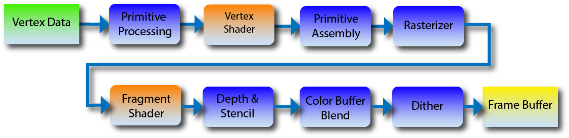
Because of the time limits I have for my course, I restrict myself to the OpenGL 2 pipeline and therefore to fragment and vertex shaders only. In newer versions of OpenGL there are other shaders, allowing, for example, to generate geometry on the fly.
Okay, in the above image all the stages we can not touch are shown in blue, whereas our callbacks are shown in orange. In fact, our main() function - is the primitive processing routine. It calls the vertex shader. We do not have primitive assembly here, since we are drawing dumb triangles only (in our code it is merged with the primitive processing). triangle() function - is the rasterizer, for each point inside the triangle it calls the fragment shader, then performs depth checks (z-buffer) and such.
That is all. You know what the shaders are and now you can create your own shaders.

Let us check the shader I listed above in the main.cpp. According to its name, it is a Gouraud shader. Let me re-list the code:
    Vec3f varying_intensity; // written by vertex shader, read by fragment shader
    virtual Vec4f vertex(int iface, int nthvert) {
        varying_intensity[nthvert] = std::max(0.f, model->normal(iface, nthvert)*light_dir); // get diffuse lighting intensity
        Vec4f gl_Vertex = embed<4>(model->vert(iface, nthvert)); // read the vertex from .obj file
        return Viewport*Projection*ModelView*gl_Vertex; // transform it to screen coordinates
    }
vayring is a reserved keyword in GLSL language, I have used varying_intensity as a name in order to show the correspondence (we will talk about GLSL in the lesson 9). In varying variables we store data to be interpolated inside the triangle, and the fragment shaders get the interpolated value (for the current pixel).
Let us re-list the fragment shader:
  Vec3f varying_intensity; // written by vertex shader, read by fragment shader
// [...]
    virtual bool fragment(Vec3f bar, TGAColor &color) {
        float intensity = varying_intensity*bar;   // interpolate intensity for the current pixel
        color = TGAColor(255, 255, 255)*intensity; // well duh
        return false;                              // no, we do not discard this pixel
    }
This routine is called for each pixel inside the triangle we draw; as an input it receives barycentric coordinates for interpolation of varying_ data. Thus, interpolated intensity can be computed as varying_intensity[0]*bar[0]+varying_intensity[1]*bar[1]+varying_intensity[2]*bar[2] or simply as a dot product between two vectors: varying_intensity*bar. In true GLSL, of course, fragment shaders receive ready interpolated values.
Notice that the shader returns a bool value. It is easy to understand what it does if we look inside the rasterizer (our_gl.cpp, triangle() function):
         TGAColor color;
            bool discard = shader.fragment(c, color);
            if (!discard) {
                zbuffer.set(P.x, P.y, TGAColor(P.z));
                image.set(P.x, P.y, color);
            }
Fragment shader can discard drawing of the current pixel, then the rasterizer simply skips it. It is handy if we want to create binary masks or whatever you want (check the lesson 9 for a very cool example of discarding pixels).
Of cause, the rasterizer can not imagine all the weird stuff you could program, therefore it can not be pre-compiled with your shader. Here we use abstract calss IShader as an intermediate between the two. Wow, it is quite rare I use abstract classes, but without it we would suffer here. Pointers to functions are ugly.
    virtual bool fragment(Vec3f bar, TGAColor &color) {
        float intensity = varying_intensity*bar;
        if (intensity>.85) intensity = 1;
        else if (intensity>.60) intensity = .80;
        else if (intensity>.45) intensity = .60;
        else if (intensity>.30) intensity = .45;
        else if (intensity>.15) intensity = .30;
        else intensity = 0;
        color = TGAColor(255, 155, 0)*intensity;
        return false;
    }
Simple modification of the Gourad shading, where the intensities are allowed to have 6 values only, here is the result:

I'll skip the Phong shading, but take a look at the article. Remember the homework assignment I gave you for texturing? We had to interpolate uv-coordinates. So, I create a 2x3 matrix. 2 rows for u and v, 3 columns (one per vertex).
struct Shader : public IShader {
    Vec3f          varying_intensity; // written by vertex shader, read by fragment shader
    mat<2,3,float> varying_uv;        // same as above

    virtual Vec4f vertex(int iface, int nthvert) {
        varying_uv.set_col(nthvert, model->uv(iface, nthvert));
        varying_intensity[nthvert] = std::max(0.f, model->normal(iface, nthvert)*light_dir); // get diffuse lighting intensity
        Vec4f gl_Vertex = embed<4>(model->vert(iface, nthvert)); // read the vertex from .obj file
        return Viewport*Projection*ModelView*gl_Vertex; // transform it to screen coordinates
    }

    virtual bool fragment(Vec3f bar, TGAColor &color) {
        float intensity = varying_intensity*bar;   // interpolate intensity for the current pixel
        Vec2f uv = varying_uv*bar;                 // interpolate uv for the current pixel
        color = model->diffuse(uv)*intensity;      // well duh
        return false;                              // no, we do not discard this pixel
    }
};
Here is the result:

Okay, now we have texture coordinates. What can we store in texture images? In fact, almost anything. It can be color, directions, temperature and so on. Let us load this texture:

If we interpret RGB values as xyz directions, this image gives us normal vectors for each pixel of our render and not only per vertex as before.
By the way, compare this image to another one, it gives exactly the same information, but in another frame:

One of the images gives normal vectors in clobal (Cartesian) coordinate system, another one in Darboux frame (so-called tangent space). In Darboux frame the z-vector is normal to the object, x - principal curvature direction and y - their cross product.
Exercise 1: Can you tell which image is represented in Darboux frame and which one is in the global coordinate frame?
Exercise 2: Can you tell which representation is better and if yes, why is that?
struct Shader : public IShader {
    mat<2,3,float> varying_uv;  // same as above
    mat<4,4,float> uniform_M;   //  Projection*ModelView
    mat<4,4,float> uniform_MIT; // (Projection*ModelView).invert_transpose()

    virtual Vec4f vertex(int iface, int nthvert) {
        varying_uv.set_col(nthvert, model->uv(iface, nthvert));
        Vec4f gl_Vertex = embed<4>(model->vert(iface, nthvert)); // read the vertex from .obj file
        return Viewport*Projection*ModelView*gl_Vertex; // transform it to screen coordinates
   }

    virtual bool fragment(Vec3f bar, TGAColor &color) {
        Vec2f uv = varying_uv*bar;                 // interpolate uv for the current pixel
        Vec3f n = proj<3>(uniform_MIT*embed<4>(model->normal(uv))).normalize();
        Vec3f l = proj<3>(uniform_M  *embed<4>(light_dir        )).normalize();
        float intensity = std::max(0.f, n*l);
        color = model->diffuse(uv)*intensity;      // well duh
        return false;                              // no, we do not discard this pixel
    }
};
[...]
    Shader shader;
    shader.uniform_M   =  Projection*ModelView;
    shader.uniform_MIT = (Projection*ModelView).invert_transpose();
    for (int i=0; i<model->nfaces(); i++) {
        Vec4f screen_coords[3];
        for (int j=0; j<3; j++) {
            screen_coords[j] = shader.vertex(i, j);
        }
        triangle(screen_coords, shader, image, zbuffer);
    }
Uniform is a reserved keyword in GLSL, it allows to pass constants to the shaders. Here I pass the matrix Projection*ModelView and its inverse transpose to transform the normal vectors (refer to the end of the lesson 5). So, computation of the lighting intensity is the same as before with one exception: instead of interpolating normal vectors we retrieve the information from the normal mapping texture (do not forget to transform light vector and normal vectors).

Okay, let us continue the fun. All the computer graphics science is the art to cheat. To (cheaply) trick the eye we use the Phong's approximation of the lighting model. Phong proposed to consider the final lighting as a (weighted) sum of three light intensities: ambient lighting (constant per scene), diffuse lighting (the one we computed up to this moment) and specular lighting.
Take a look at the following image, it speaks for itself:

We compute diffuse lighting as a cosine of the angle between the normal vector and the light direction vector. I mean, this supposes that the light is reflected in all directions uniformly. What happens to glossy surfaces? In the limit case (mirror) the pixel is illuminated if and only if we can see the light source reflected by this pixel:

For diffuse lighting we computed the (cosine of) angle between vectors n and l, and now we are interested in the (cosine of) angle between vectors r (reflected light direction) and v (view direction).
Exercise 3: Given vectors n and l, find vector r.
Answer: If n and l are normalized, then r = 2n<n,l> - l
For diffused lighting we computed the light intensity as the cosine. But a glossy surface reflects in one direction much more than in others! Okay then, what happens if we take tenth power of the cosine? Recall that all numbers inferior to 1 will decrease when we apply the power. It means that tenth power of the cosine will give smaller radius of the reflected beam. And hundredth power much smaller beam radius. This power is stored in a special texture (specular mapping texture) that tells for each point if it is glossy or not.
struct Shader : public IShader {
    mat<2,3,float> varying_uv;  // same as above
    mat<4,4,float> uniform_M;   //  Projection*ModelView
    mat<4,4,float> uniform_MIT; // (Projection*ModelView).invert_transpose()

    virtual Vec4f vertex(int iface, int nthvert) {
        varying_uv.set_col(nthvert, model->uv(iface, nthvert));
        Vec4f gl_Vertex = embed<4>(model->vert(iface, nthvert)); // read the vertex from .obj file
        return Viewport*Projection*ModelView*gl_Vertex; // transform it to screen coordinates
    }

    virtual bool fragment(Vec3f bar, TGAColor &color) {
        Vec2f uv = varying_uv*bar;
        Vec3f n = proj<3>(uniform_MIT*embed<4>(model->normal(uv))).normalize();
        Vec3f l = proj<3>(uniform_M  *embed<4>(light_dir        )).normalize();
        Vec3f r = (n*(n*l*2.f) - l).normalize();   // reflected light
        float spec = pow(std::max(r.z, 0.0f), model->specular(uv));
        float diff = std::max(0.f, n*l);
        TGAColor c = model->diffuse(uv);
        color = c;
        for (int i=0; i<3; i++) color[i] = std::min<float>(5 + c[i]*(diff + .6*spec), 255);
        return false;
    }
};
I think that i do not need to comment anything in the above code at the exception of coefficients.
for (int i=0; i<3; i++) color[i] = std::min<float>(5 + c[i]*(diff + .6*spec), 255);I took 5 for the ambient component, 1 for the diffuse component and .6 for the specular component. What coefficients to choose - is your choice. Different choices give different appearances for the object. Normally it is for the artist to decide.
Please note that normally the sum of the coefficents must be equal to 1, but you know. I like to create light.


We know how to render quite nice scenes, but our lighting is far from being real. In the next articles I will talk about shadows.
Enjoy!