BirdWatcher IoT Device Assembly Instructions - marekt77/BirdWatcher GitHub Wiki
Hi! This step-by-step document will help guide you through the process of building your own BirdWatcher IoT device. Please refer to the Parts List and Tools list for a quick reference of what is required to follow this guide. If you have any questions or find any errors, please feel free to drop me an email, or create a issue on GitHub and I’ll try to help you out.
1. Disassembling Log Cabin
Start by disassembling the Log Cabin Birdfeeder. Pictured below:

First, you need to take off the bottom base. Place the cabin on its side, with the tabs in the following position:

You want to lay the cabin near the edge of your table, with the bottom base overhanging the edge. Once it is in position, gently tap at the top of the base, and it should slide down, allowing you to pull off the base. This will allow you to pull the base off. Do not use a hammer as it might crack the plastic base.
With the base off, the cabin should look like this:

Now it’s time to remove the top and bottom walls of the cabin. (The long walls with two windows in them).
The walls are slotted into two side walls and are held on top by a latch. Unfortunately, there is no quick and easy way to remove these walls. The good news is that the plastic is flexible and will not crack easily. The best way I found was the pull part the side wall, while pulling up on the long wall. Take your time and feel it out yourself.
Eventually it should look like this:

At this point all that is left is to remove the wall from the notch. Again, this will require some pulling and pushing.
Once the two long walls have been removed, you can start mounting the various parts onto them.

2. Mounting the Raspberry Pi
You need to drill two 7/64 holes in two of the 2x8 Lego flat plate. The holes should be in the top and bottom circles on the bottom of the piece. See the picture:

Once the holes are made, you need to get 4 of the 1.5mm nylon spacers and attach them to the 4 holes on the Raspberry Pi. Next, you attach the spacers to the Lego Plates using the holes you just drilled. The end result should look like the pictures below:


Now that the Raspberry Pi is attached to the Lego pieces, take two more 8x2 flat plates, and snap them onto the ones attached to the Pi. With everything attached, take the Pi, and place it on one of the walls you removed from the birdfeeder. Align it with the USB power connector facing downwards. It should look like the picture below:

With the Pi placed on the wall, mark off where the flat plates are seated on the wall. Now remove the two bottom plates from the Pi and place them on again on the wall on the marks you made.
 (Note: make sure the pieces are properly aligned)
Now you will use the glue gun, and glue the these pieces to the wall. You can use an addition plate to help you place them and not burn your figures. Apply the glue as shown in the picture:

Once the glue dries, you can attach the Pi to the wall. The result should look like this:
3. Attaching the Breadboard
Now we will attach the breadboard with the sensor connectors to the opposite wall. The breadboard had two holes, and again we will attach two 1.5mm nylon spacers. For the breadboard we will reverse the application. The female end will go up against the breadboard, and the two nylon screws will secure the breadboard to the spacers.
Take two 2x8 flat Lego plates, and drill two 7/64 holes in them. Next take two more 2x8 flat Lego plats, and attached them perpendicular to the plates attached to the breadboard. Since you are using the nylon nuts to secure the breadboard to the plate. Cut off any excess thread so the but is evenly flat with the plate. Now place them on the other wall of the birdhouse and mark their locations. Note: due to the placement of the holes on the breadboard, this will not be an exact fit like the Pi. The breadboard will be angled. See the picture below:

Mark the location of the base pieces. Remove the breadboard, and just like the Pi, use the glue gun to glue the pieces to the wall. Once the glue dries, attach the breadboard to the wall. The result should look like the picture above.
4. Attaching the Camera
Note: The camera might not be properly focused, so before taking this step run the camera on a Pi and make sure the focus is set correctly.
Next you will attach the camera. Take the Raspberry Pi camera module, and put it into the Smarticase Pi case, and connect the ribbon cable. With the camera in its case, attach 2 2mm nylon spacers to the case.
Now take one 2x8 flat Lego plate, and drill two 7/64 holes in them. The holes should in the location shown in the picture below. Now screw in the nylon screws to attach the camera to the plate. The result should look like this:

You are going to attach the camera on bottom of the window. Attach another flat piece to the camera module. The Lego piece should be aligned on the side of the window. Make sure the camera is not blocked by the window frames. Feel free to attach it to whatever window you plan on pointing towards your subjects. Mark where the piece will be glued. Take off the camera, and glue on the base to the wall. Once the glue is dried, attach the camera module.
5. Attach the Temperature sensor.
First, you are going to drill a 7/16th inch hole right below the point of the roof. See the picture below:

Now put in the temperature sensor through the hold. Use the glue gun to glue the sensor in place. The result should look like this:

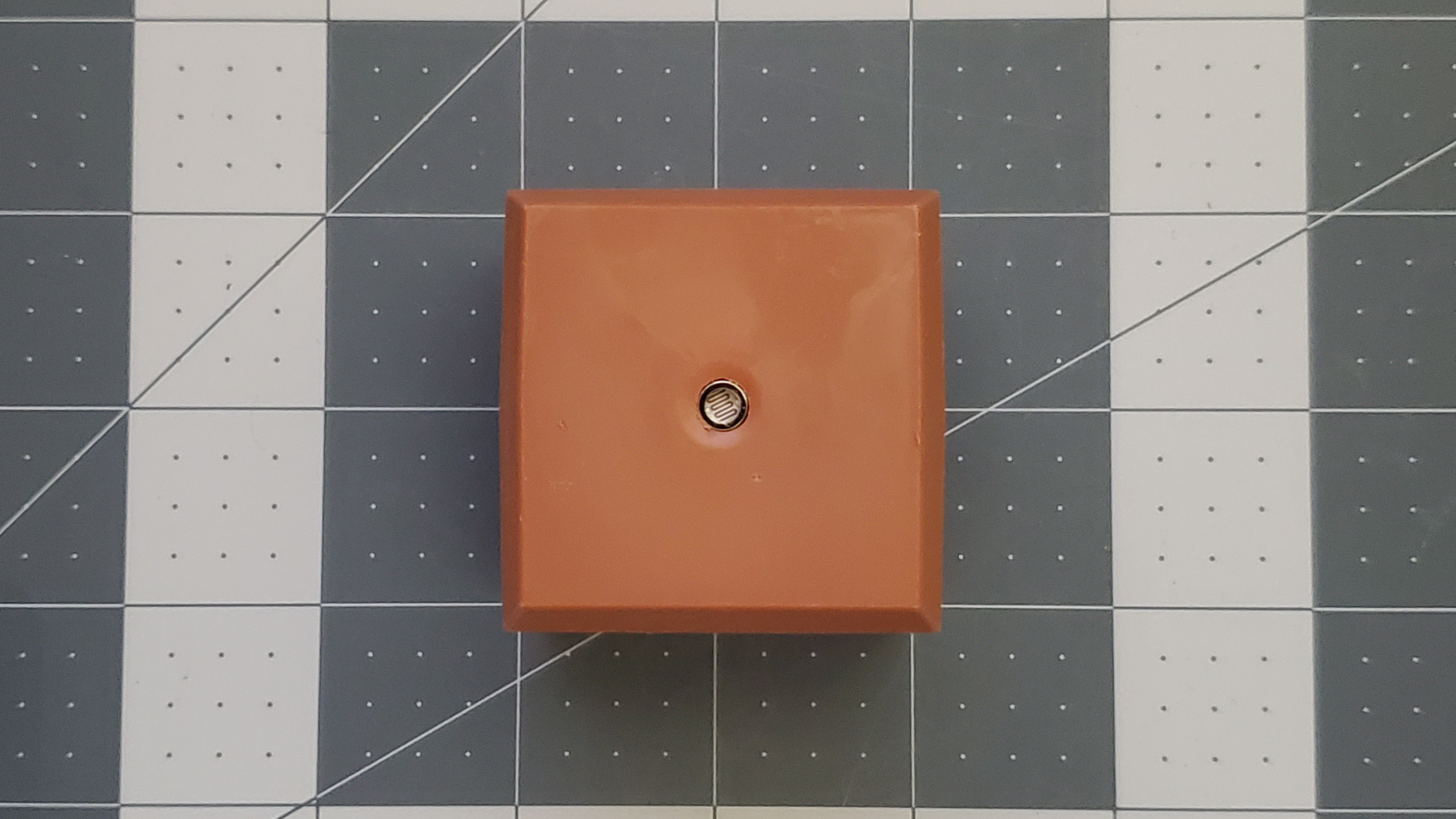
6. Attach the light sensor
Take the Sunfounder Photoresistor light module and solder off the sensor that came with it. Once it is off,solder on the water-resistant photoresistor. Now take two 1.5mm nylon spacers and attach them to photoresistor.
Next, take one 2x8 flat Lego plate, and cut it in half. Take one half, and drill two holes into it where the module will attach two.

Now remove the chimney from the birdhouse and drill a 7/32-inch hole in the center. Take the photoresistor and place it in the hole. Use a glue gun to secure it to the chimney. The result should look like this:
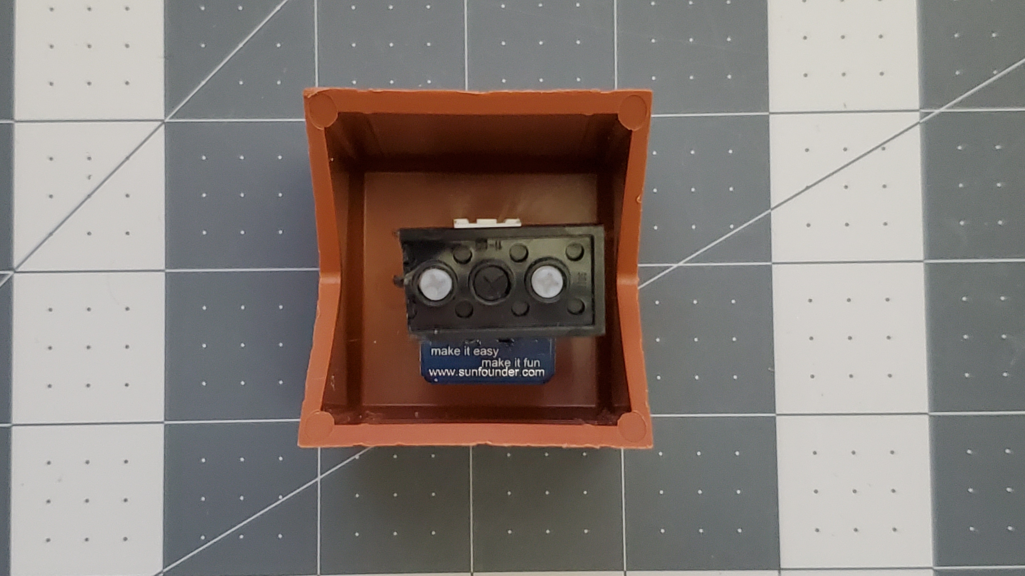
Place the chimney back into the birdhouse. Now attach the 2nd half of the Lego plate, and attach it to the module. Now glue the module to the inside of the birdhouse. It should look like this:


7. Attach the power cable.
Take the base of the house, and drill a 1/2 inch hole in the bottom of the base.
Next drill a 7/16 in hole on one of the fins from the center cylinder. Put a quick tie through the hole, and secure the power cable. The end result should look like this:

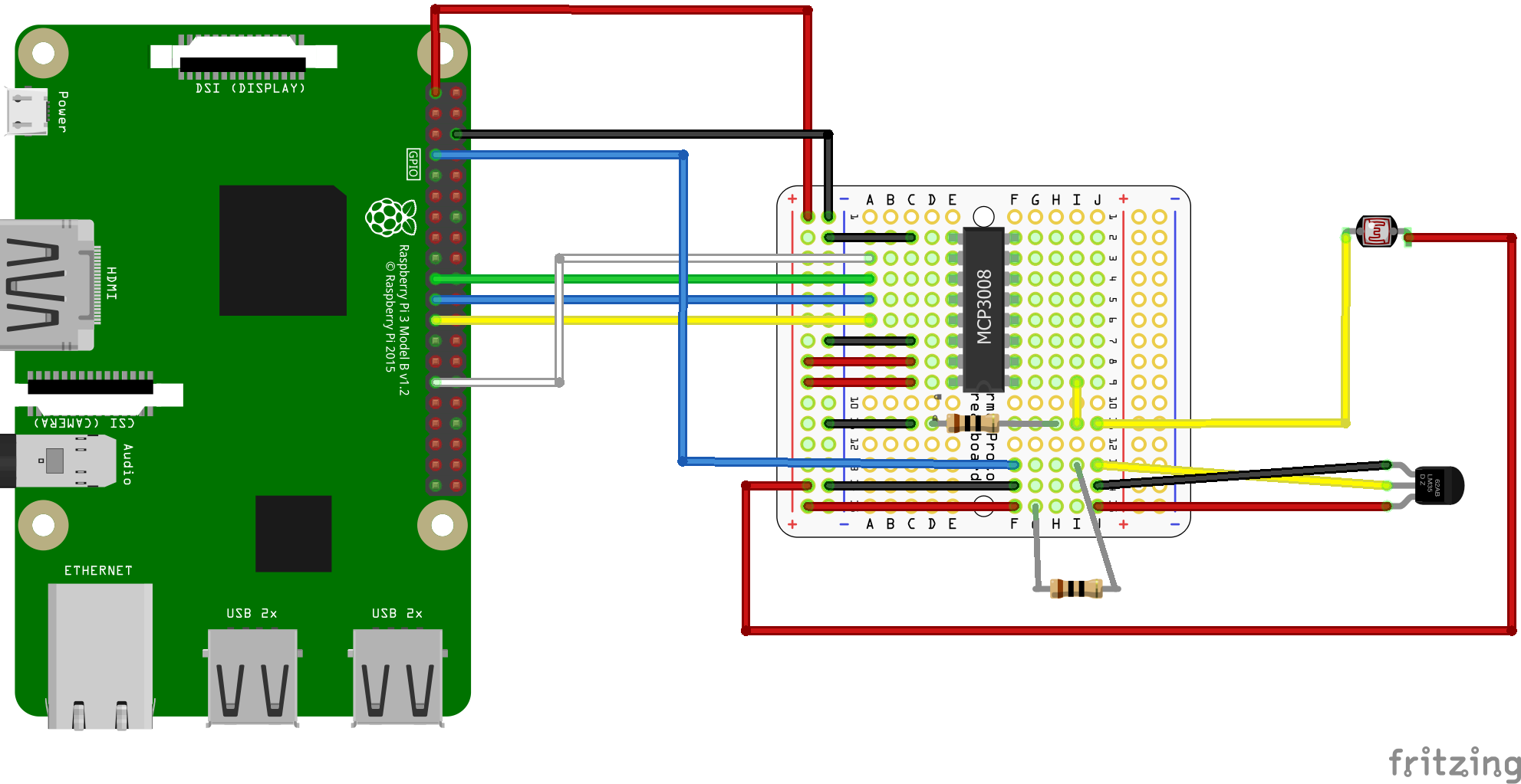
8. Attach all the cables to the Pi.
Use the following diagram as reference on how to hook up the cables to the Pi:
9. Reassemble the house.
Now reassemble the house. Again, there is no right way to do this, just feel it and snap the walls back into place. Now attach the base back to the house. Once the house is assembled, you can use clear silicone weather seal around all the outside edges to fully weatherproof the device. Do not seal the bottom base, so you can remove it in the future.
10. Install the house outside
Now install the house outside, and make sure the camera is pointed towards the birdfeeder that you want to capture the birds from. I mounted mine on a ¾ inch PVC pipe, close to a window so I can power the unit easily:
