Camera driver notes - madisongh/meta-rk3588 GitHub Wiki
Based on a machine-translated copy of Rockchip_Driver_Guide_VI_CN_v1.1.1.pdf. Covers device tree configuration only, and only for RK3588/RK3588S. Has some paraphrasing/rewording for clarity, hopefully without loss of accuracy.
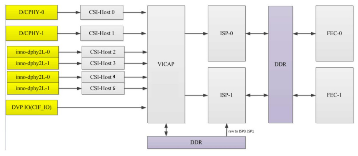
- One VICAP
- MIPI dphy configured as either 4 2-lane interfaces or 2 4-lane interfaces, 2.5Gbps/lane
- MIPI dcphy configured as either 4 2-lane dphy or 2 3-lan cphy interfaces, 2.5Gbps/lane
- DVP: BT610/BT656/BT1120 pclk 150MHz
- 4672x3504 single ISP, 8192x6144 dual ISP synthesis
- Up to 3 frames of HDR
- One VICAP
- MIPI dphy configured as either 2 2-lane interfaces or 1 4-lane interface, 2.5Gbps/lane
- MIPI dcphy configured as either 2 4-lane dphy or 2 3-lan cphy interfaces, 2.5Gbps/lane
- DVP: BT610/BT656/BT1120 pclk 150MHz
- 4672x3504 single ISP, 8192x6144 dual ISP synthesis
- Up to 3 frames of HDR
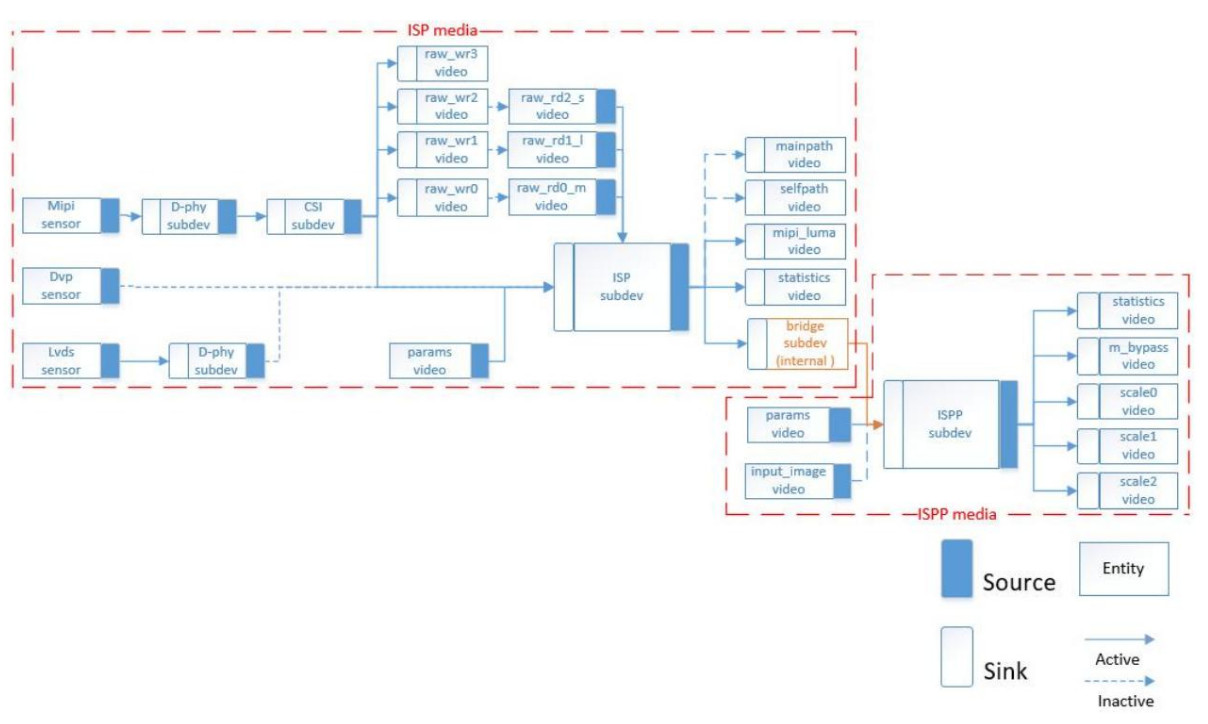
| Name | Type | Description |
|---|---|---|
| rkisp_mainpath | v4l2_vdevcapture | YUV or RAW format, supports cropping |
| rkisp_selfpath | v4l2_vdevcapture | YUV or RGB format, supports cropping |
| rkisp-isp-subdev | v4l2_subdev | Internal ISP blocks. Format/size on sink pad match sensor format/size. Format on source pad should be RAW if vdev output format is RAW, otherwise YUYV2X8. Source pad size should be <= sink pad size. |
| rkisp-mip-front | v4l2_vdevcpature | Provides raw image luma |
| rkisp-statistics | v4l2_vdevcapture | Provides image color statistics |
| rkisp-input-params | v4l2_vdevoutput | Accepts parameters for AWB and other image enhancement blocks |
| rkisp_rawrd0_m | v4l2_vdevoutput | Raw image read from DDR to ISP, used for HDR middle frame |
| rkisp_rawrd1_l | v4l2_vdevoutput | Raw image read from DDR to ISP, used for HDR long frame |
| rkisp_rawrd2_s | v4l2_vdevoutput | Raw image read from DDR to ISP, used for HDR short frame |
| rkisp-csi-subdev | v4l2_subdev | MIPI-CSI configuration |
| rkisp_rawwr0 | v4l2_vdevcapture | Raw image write from sensor to DDR, used for HDR middle frame |
| rkisp_rawwr1 | v4l2_vdevcapture | Raw image write from sensor to DDR, used for HDR long frame |
| rkisp_rawwr2 | v4l2_vdevcapture | Raw image write from sensor to DDR, used for HDR short frame |
| rkisp_rawwr3 | v4l2_vdevcapture | Raw image write from sensor to DDR |
| rockchip-mipi-dphy-rx | v4l2_subdev | MIPI-DPHY configuration |
| rkisp-bridge-ispp | v4l2_subdev | ISP output to ISPP (YUV) |
| rkisp-ispp-subdev | v4l2_subdev | Format and size on sink pad == ISP output, max 4416x3312, min 66x258 |
| rkispp_m_bypass | v4l2_vdevcapture | Full resolution, YUV format |
| rkispp_scale0 | v4l2_vdevcapture | YUV format, full or scaled resolution (range 1-8 ratio). Max width 3264 (YUV422), 2080 (YUV420) |
| rkispp_scale1 | v4l2_vdevcapture | YUV format, full or scaled resolution (range 2-8 ratio). Max width 1280 |
| rkispp_scale2 | v4l2_vdevcapture | YUV format, full or scaled resolution (range 1-8 ratio). Max width 1280 |
The RK3588 supports two DCPHYs, node names csi2_dcphy0 and csi2_dcphy1. Each DCPHY supports
simultaneous use of RX/TX, and RX is used for camera input. The hardware supports DPHY/CPHY protocol multiplexing; it should be noted that
the TX/RX of the same dcphy can only use DPHY or CPHY at the same time. For other
DCPHY parameters, please refer to the RK3588 data sheet.
The RK3588 supports 2 DPHYs, dphy0_hw and dphy1_hw, which support "full" and "split" modes.
- Full mode: The node name used is
csi2_dphy0, and supports up to 4 lanes. - Split mode: split into two phys for use, named
csi2_dphy1(lanes 0 and 1) andcsi2_dphy2(lanes 2 and 3). Each phy supports up to 2 lanes.
When configuring dphy0_hw for full mode, the link needs to be configured on csi2_dphy1, but the node name csi2_dphy1 needs to be changed to csi2_dphy0, so the software can identify that full mode is being used.
- Full mode: The node name used is
csi2_dphy3, and supports up to 4 lanes. - Split mode: split into two phys for use, named
csi2_dphy4(lanes 0 and 1) andcsi2_dphy5(lanes 2 and 3). Each phy supports up to 2 lanes
When configuring dphy1_hw for full mode, the link needs to be configured according on csi2_dphy4, but the node name
csi2_dphy4 needs to be changed to csi2_dphy3, so the software can identify that full mode is being used.
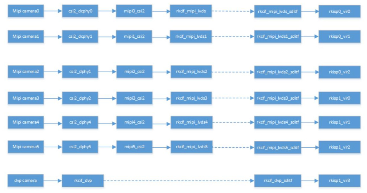
- To use the above MIPI PHY nodes, you need to configure the corresponding physical node (
csi2_dcphy0_hw/csi2_dcphy1_hw/csi2_dphy0_hw/csi2_dphy1_hw). - Each MIPI PHY needs a CSI2 module to parse the MIPI protocol (node names
mipi0_csi2throughmipi5_csi2). - All camera data needs to pass through VICAP, and then link to ISP. RK3588 has one VICAP hardware, which supports up to 7 simultaneous input channels, 6 MIPI (node names
rkcif_mipi_lvds0throughrkcif_mipi_lvds5) and 1 DVP (rkcif_dvp). The binding relationship of each node needs to be strictly in accordance with the block diagram node numbering. - The link relationship between each VICAP node and the ISP is indicated by corresponding virtual XXX_sditf.
- The RK3588 has 2 ISP hardware blocks. Each ISP can supports multiple virtual nodes; the software reads the image data of each channel from the DDR in turn through the read-back method. For a multi-camera setup, it is recommended to evenly distribute the data streams between the two ISPs.
The ISP blocks support "pass-through" (or "straight-through") and "read-back" modes.
- Pass-through: Image data passes directly from VICAP to ISP without intermediate storage in DDR. It should be noted that during HDR pass-through, only short frames are true pass-through, long frames need to exist in DDR, and the ISP reads from DDR.
- Readback: refers to the data collected by VICAP to DDR. After the application obtains the data, it pushes the buffer address to the ISP, and the ISP then obtains the image data from DDR.
When configuring the device tree, if an ISP is only configured with one virtual node, the pass-through mode is used by default, and if multiple virtual nodes are configured, the readback mode is used.
Example DTS fragment for configuring an IMX464 sensor connected to DPHY1.
/{
	vcc_mipicsi1: vcc-mipicsi1-regulator {
		compatible = "regulator-fixed";
		gpio = <&gpio4 RK_PA6 GPIO_ACTIVE_HIGH>;
		pinctrl-names = "default";
		pinctrl-0 = <&mipicsi1_pwr>;
		regulator-name = "vcc_mipicsi1";
		enable-active-high;
	};
};

&csi2_dphy1_hw {
	status = "okay";
};

&csi2_dphy3 {
	status = "okay";
	ports {
		#address-cells = <1>;
		#size-cells = <0>;
		port@0 {
			reg = <0>;
			#address-cells = <1>;
			#size-cells = <0>;
			mipi_in_ucam: endpoint@1
			{
				reg = <1>;
				remote-endpoint = <&imx464_out>;
				data-lanes = <1 2 3 4>;
			};
		};
		port@1 {
			reg = <1>;
			#address-cells = <1>;
			#size-cells = <0>;
			csidphy3_out: endpoint@0
			{
				reg = <0>;
				remote-endpoint = <&mipi4_csi2_input>;
			};
		};
	};
};


&i2c4 {
	status = "okay";
	pinctrl-0 = <&i2c4m3_xfer>;
	imx464: imx464@36 {
		compatible = "sony,imx464";
		status = "okay";
		reg = <0x36>;
		clocks = <&cru CLK_MIPI_CAMARAOUT_M4>;
		clock-names = "xvclk";
		pinctrl-names = "default";
		pinctrl-0 = <&mipim0_camera4_clk>;
		avdd-supply = <&vcc_mipicsi1>;
		reset-gpios = <&gpio1 RK_PD6 GPIO_ACTIVE_HIGH>;
		pwdn-gpios = <&gpio3 RK_PC1 GPIO_ACTIVE_HIGH>;
		rockchip,camera-module-index = <0>;
		rockchip,camera-module-facing = "back";
		rockchip,camera-module-name = "CMK-OT1980-PX1";
		rockchip,camera-module-lens-name = "SHG102";
		port {
			imx464_out: endpoint {
				remote-endpoint = <&mipi_in_ucam>;
				data-lanes = <1 2 3 4>;
			};
		};
	};
};

&mipi4_csi2 {
	status = "okay";
	ports {
		#address-cells = <1>;
		#size-cells = <0>;
		port@0 {
			reg = <0>;
			#address-cells = <1>;
			#size-cells = <0>;
			mipi4_csi2_input: endpoint@1 {
				reg = <1>;
				remote-endpoint = <&csidphy3_out>;
			};
		};
		port@1 {
			reg = <1>;
			#address-cells = <1>;
			#size-cells = <0>;
			mipi4_csi2_output: endpoint@0 {
				reg = <0>;
				remote-endpoint = <&cif_mipi_in4>;
			};
		};
	};
};


&pinctrl {
	cam {
		mipicsi1_pwr: mipicsi1-pwr {
			rockchip,pins = /*camera power en */ <4 RK_PA6 RK_FUNC_GPIO &pcfg_pull_none>;
		};
	};
};

&rkcif
{
	status = "okay";
};

&rkcif_mipi_lvds4 {
	status = "okay";
	port { cif_mipi_in4: endpoint {
			remote-endpoint = <&mipi4_csi2_output>;
		};
	};
};

&rkcif_mipi_lvds4_sditf {
	status = "okay";
	port {
		mipi4_lvds_sditf: endpoint {
			remote-endpoint = <&isp0_vir0>;
		};
	};
};

&rkcif_mmu {
	status = "okay";
};

#if 1
&rkisp0 {
	status = "okay";
	/* the max input wh and fps of multi sensor */
	//max-input = <2688 152030 >; /* multi-cam sensor resolution is different, need to configure */
};

&isp0_mmu {
	status = "okay";
};
#else
 /*
  * Sensor resolution greater than 16M (4672x3504) requires 2 isp composite
  * processing, only supports single camera
  * Dual isp case need width 32 align
  */
&rkisp_unite_mmu {
	status = "okay";
};

&rkisp_unite {
	status = "okay";
};

&rkisp0_vir0 {
	status = "okay";
	rockchip,hw = <&rkisp_unite>;
};
#endif

&rkisp0_vir0 {
	status = "okay";
	port {
		#address-cells = <1>;
		#size-cells = <0>;
		isp0_vir0: endpoint@0 {
			reg = <0>;
			remote-endpoint = <&mipi4_lvds_sditf>;
		};
	};
};
-
data-lanesmust specify the number of lanes used, otherwise it cannot be recognized as MIPI type - dphy needs to be linked to the csi host node, and
csi2_dphy3corresponds tomipi4_csi2;csi2_dphy3is only a logical node and needs to rely on the physical nodecsi2_dphy1_hw -
rkcif_mipi_lvds4is one of the logical nodes of VICAP, and the physical noderkcifand the correspondingiommuneed to be configured. *rkcif_mipi_lvds4_sditfis a virtual child node, a virtual node ofrkcif_mipi_lvds4, used to link to the ISP.
The sensor driver generally implements the three power supply operations: avdd, dvdd, and dovdd. If you use a power supply similar to the RK809, you can configure it directly on the sensor node. If you use an external power supply such as an LDO, the enable pin is controlled by a GPIO. You can refer to vcc_mipicsi1 to configure it. The power node can be powered on and off by
reference counting, which is suitable for multiple devices using the same power supply.
It is recommended to supply the dvdd power supply separately when multiple cameras are used. Avdd/dovdd can be shared. When dvdd is shared, if the power draw is relatively large, there may be a momentary shortage of supply, which will affect the image quality and even fail to produce pictures.