Standalone Power Relays - madBeavis/PimpMyAtv GitHub Wiki
Builds
Several example relay setups are outlined below. Don't be afraid to ask questions.
Do your homework prior to purchasing as these are entering the realm of advanced setups and some of the hardware is not documented well, if at all. Each type has detractions and benefits, but they also could also change depending on your circumstances, i.e. money available vs time/desire to tinker.
Namuto
- Build outline of my build
- 32 channel ethernet relay
- The one I used operates through telnet over TCP/IP, Numato makes other options for interface with board
- Programming examples in several languages. Look through others as the python one seems lacking compared to others.
- Numato has its own program that is a basic home control type one, called Rhea, basic on/off functionality.
- Python scripts
- v1 is functional for what I need, i.e. controlling from command line, checking status of relay and cron jobs.
- v2 is being designed to handle NO vs NC wiring and adjust accordingly, i.e. when you turn off an ATV, it handles it for you without you remembering whether the relay is set as NC or NO presuming you set the options properly in the file.
- Be kind, python hates me as much as I hate it.
- Verified working with RebootMadDevice by GhostTalker on my setup
Hi-Link
- Amazon - Hi-Link Ethernet 16 relays
- Operates via a http interface over TCP/IP
- Manual
- Bash scripts
- PurseChicken is using this item and has been kind enough to share his work
- Repository
- RebootMadDevice by GhostTalker
Arduino based build
- Build info by rjgeyer
- Could do the build with a pi also, since it uses GPIO
- Economical, the relay costs $12us for 16.
- Could replicate with a similar setup using Raspberry Pi
Raspberry Pi
- Several folks have used for their MAD setups, ask in the appropriate Discord channels
- Using GPIO - Not an ATV example, but one could easily adapt this to work for ATV
- Plenty of other examples found via googling. Seems like a lot of tinkering from my perspective compared to near plug and play you get from the Numato and Hi-Link setups, but if that is your thing I can't stop you.
- Expansion beyond standard GPIO count for Pi, things get more complicated. One can do 200+ ATV setup off of a Hi-Link or Numato setup with multiple board, things would get interesting fast on a Pi setup.
Home Automation Relays
- Theoretically it is possible to use whatever relays you want, as long as you can figure it out. Plenty of options, but many lack reasonably useful documentation, that is if you can find it. If you love tinkering and willing to put in the work yourself, by all means try it. If you are looking for more of an out of the box solution, consider other options, as you will likely be on your own. So do your homework.
- Example products that could be considered:
APC Rack PDU
While not a relay, the APC PDU can individually control power to the outlets. They are available in 8, 16 and 24 port configurations and while discontinued by the manufacturer, they can be found on ebay.
Why use power relays?
To some, the whole idea of this seems complicated. You don't need to know the inner workings of relays or be super competent with electrical projects. There are no step by step ATV instructions or videos to watch, but there is people around to guide you through the process from design to implementation. Since this is an advanced topic, it will be expected for one wanting to embark on the relay journey, it won't be as simple as auto-config of an ATV.
The reason to do use power relays is to provide unmatched reliability in your system - no more having ATVs that aren't doing something between jack and shit, just consuming electricity. MAD will handle restarts when its criteria is satisfied, but we all know that reboots don't resolve all issues with ATVs. However, a power cycle will resolve the issue near 100% of the time (excluding google issues), but it is time to work smarter not harder.
Get the setup done right and run GhostTalker's scripts, the system will handle the prior for you. The script gets the device's status from MAD and if the ATV hasn't sent data to MAD in the set time frame, it power cycles the device. No more waking up to have ATVs that haven't done any work since 12:18 in the morning. No more having to go home to power cycle devices. No more getting off the couch to power cycle a device. No more using phone control to force a reboot and hope it fixes the problem. And most importantly, no more asking the spouse to pull plug #6 in your setup. It is as close to fire up and forget as you can get with MAD and ATVs.
Which one is right for you?
I don't know all the details of your setups or your desires. All I can do is explain why I chose the Numato board for my setup. What puts the Numato in the plus column for me could put it in the negative column for you.
I run my system locally with a laptop running MAD. I tried the VPS based solution, but my internet is too crappy for it to work right. Therefore, I am able to run the Numato or Hi-Link boards without the requirement of other hardware as it runs on my MAD laptop. If I wanted to run the Pi based relays, that would be another piece of equipment to purchase and rely upon. Had I used a VPS based solution, I would have probably ran a Pi to control the Numato. I knew that I wanted more ATVs that a stock Pi based system offered and I hate soldering, so a Pi based relay was not an option.
Time is money. I wanted the simplest solution, so that is worth paying a higher dollar amount for a straightforward solution. One board, one answer, simple as that. The Numato baord was $180 for 32 relays. The Hi-Link is $60 for 16 relays, so $120 for 32. Given the space constraints (I couldn't stack or layout 2x Hi-Link) for my build and time is money, it was an easy choice.
For those of you that run a VPS solution and house ATVs at other locations, the Pi based solution could make sense. For me, I would probably still run a Numato or Hi-Link on a Pi vs Pi/GPIO setup). If I was to do such a thing, I would have 8-16 ATVs setup in a computer case, so the recipient just has to plug in power and hook a RJ-45 into their home network. Inside the case I would have a cheap router and a switch, too hookup and fix ip addresses. There would be a Raspberry Pi to run GhostTalker's scripts and relays. A couple of power supplies (12v and 5v) plus power blocks to distribute and protect devices with fuses.
Basic example setup
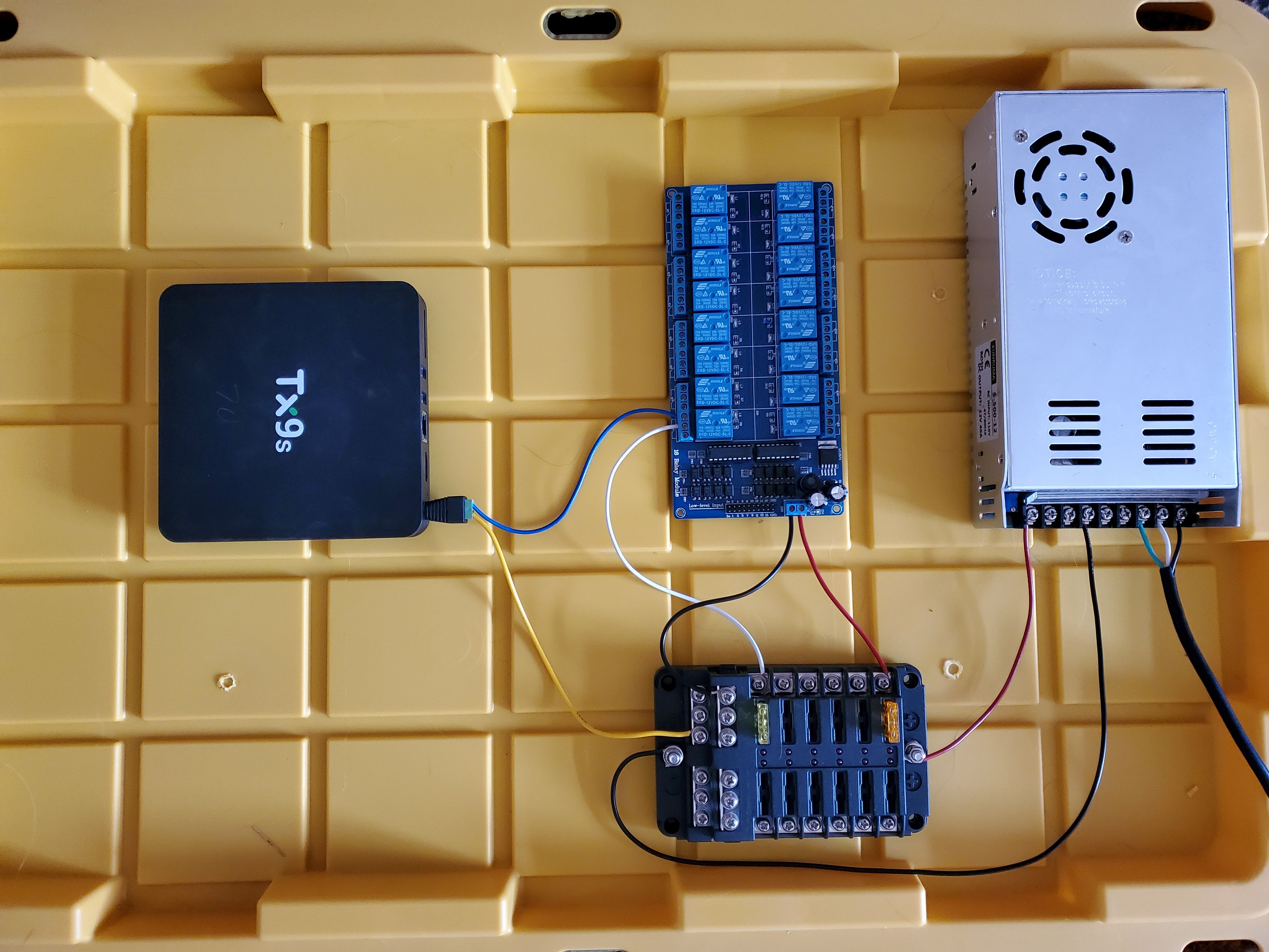
If you are new to relays or don't quite understand how one would wire the parts up for a MAD setup, this section is for you. Read along while referencing the picture.

The picture is a basic 12v only relay setup one could use for say a tx9s setup with minimal wiring. Hopefully this illustrate how things are hooked up with as few components as possible with the goal to make things simple to comprehend. A fellow member of MAD had wanted to get some relays for his ATVs, so I whipped this physical demo setup up to show him how it was done in about 30 minutes in the hope that it would also help others in the future. It is not production ready, but is done for illustrative purposes to show folks how a relay setup can be done. The components are as follows:
- Upper right shiny box - 12v 40a power supply unit aka PSU
- Middle upper - Hi-Link clone 12v ethernet relay board with 16 relays
- I did not put the ethernet add-on board on it to keep things simpler
- 12v refers to what voltage you feed into the logic and/or relay activation
- For this example, I would also be using 12v to feed power to the ATV. You can put a range of voltages into the relays, of course within board specifications defined in the manual.
- Middle lower - 12 hookup fuse/distribution block
- Left - tx9s atv
The wiring of how things are hooked up as follows, going from the PSU to the ATV. I did not have enough colors of wires as I figured, but I think the quantity I had available will suffice. I would also not use such small gauge wiring from the PSU to fuse block, but I think the 18 gauge I used will suffice for the purpose of this exercise. The wiring description is as follows:
- 120v (or local wall power) to PSU - black wire that feeds into the PSU
- Standard computer power cord with female end cut off
- These PSU don't come with manuals, but there are small diagrams on the end of the PSU above the terminal strip that outline what their individual functions are. Check and double check prior to providing the PSU power.
- for the USA 120v = ground - green / neutral - white / hot - black
- refer to directions on the internet how to hook up to your specific local power standard
- PSU to fuse block
- red is positive 12v - this PSU has 3x positive hookups, which are the left ones on the PSU terminal strip
- black is ground - this PSU has 3x ground hookups, the middle ones on the terminal strip
- This fuse block is just one of many configurations available. The 12v power comes in from the PSU, goes through the fuse and then out to the individual hookups.
- Fuse block to 12v relay board
- Red is positive 12v
- Black is ground
- Board variations
- Check your board for voltage requirements, I have seen options of 5v, 12v and 24v for relay activation
- Some boards like Numato have 2x power feeds, one for logic and one for relay activation. So rtfm before making wiring decisions because I didn't and my Numato didn't fire up immediately. There may also be jumpers that you need to configure.
- Fuse block to individual relay feed
- White wire provides 12v to the relay we are using
- Relay to ATV
- Blue wire is hooked to NO (normally open) on the relay and positive input on the barrel connector (inside portion of barrel)
- Fuse block to ATV
- Yellow wire is hooked to negative on the fuse block and negative on the barrel connector (outside portion of barrel)
- Barrel connector plugs into ATV, with positive on the inside of barrel and negative on the outside