ESP‐12E - lvidarte/esp8266 GitHub Wiki
The ESP-12E has a ESP8266 core processor, with a module of 4MB of flash memory. Also it has 22 pins and a on board printed antenna. It also has a built-in LED which is directly connected to the UART TX line. You can use the TX pin as GPIO1 to control the LED, but only if you don't use UART.
Dimensions: 24mm x 16mm
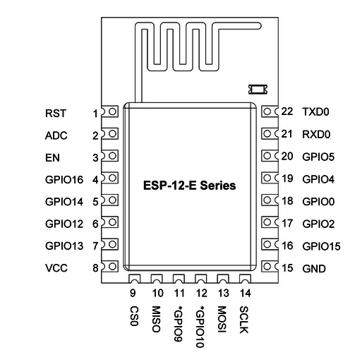
ESP-12E Pinout
https://raw.githubusercontent.com/lvidarte/esp8266/master/examples/rgb-lamp/esp12e-pinout.jpg
ESP8266 Bootloader Modes
The bootloader can go into a number of modes depending on the state of GPIOs 0, 2 and 15. The two useful modes are the UART download mode (for flashing new firmware) and the flash startup mode (which boots from flash).
| Mode | GPIO0 | GPIO2 | GPIO15 |
|---|---|---|---|
| UART Download Mode (Programming) | 0 | 1 | 0 |
| Flash Startup (Normal) | 1 | 1 | 0 |
| SD-Card Boot | 0 | 0 | 1 |
CH_PD (or EN) Chip enable. Should be high for normal operation.