Tinker Developer Guide - longge-lee/doc_test GitHub Wiki
- For Tinker Board 2 / Tinker Board 2S
-
Installing the build tools
$ sudo apt-get install git-core gitk git-gui gcc-arm-linux-gnueabihf device-tree-compiler gcc-aarch64-linux-gnu mtools parted libssl-dev -
Build Kernel
$ cd [source code]
$ make ARCH=arm64 tinker2_defconfig
$ make ARCH=arm64 rk3399-tinker_board_2.img CROSS_COMPILE=aarch64-linux-gnu- -j8
You will get boot.img in the directory of kernel after build success.
-
Install Kernel
Copy the boot.img to Tinker Board 2.
Use the command to install boot.img.$ sudo dd if=boot.img of=/dev/mmcblk1p4 status=progress && sync $ sudo rebootEx:

Note:
- Image in eMMC
sudo dd if=boot.img of=/dev/mmcblk1p4 status=progress && sync - Image in SD Card
sudo dd if=boot.img of=/dev/mmcblk0p4 status=progress && sync
- Image in eMMC
-
Install Docker environment
-
Uninstall old versions
$ sudo apt-get remove docker docker-engine docker.io containerd runc -
Install Docker Engine – Community
$ sudo apt-get update $ sudo apt-get install apt-transport-https ca-certificates curl gnupg-agent software-properties-common $ curl -fsSL https://download.docker.com/linux/ubuntu/gpg | sudo apt-key add - $ sudo apt-key fingerprint 0EBFCD88 $ sudo add-apt-repository "deb [arch=amd64] https://download.docker.com/linux/ubuntu $(lsb_release -cs) stable" $ sudo apt-get update $ sudo apt-get install docker-ce docker-ce-cli containerd.io $ sudo docker run hello-world -
Manage Docker as a non-root user
$ sudo groupadd docker
$ sudo usermod -aG docker $USER
$ newgrp docker
$ docker run hello-world
Reference: https://docs.docker.com/engine/install/linux-postinstall/
-
-
Code compiling
- Go to the directory where you have downloaded the code base and execute the script. This will take a while to install the necessary packages on the host and build the Docker image.
Once the above is done, you are in the shell of the newly started Docker container as the following.
$ ./docker_builder/docker-builder-run.sh
You can start to issue commands as usual.Successfully built 702bff5a9b3f Successfully tagged asus/tinker_2-linux-builder:latest Options to run docker: --privileged --rm -it --volume /DIRECTORY_PATH_TO_SOURCE:/source your_usernmae@292c696527f6:/source$ - You can issue the following command to build all the images for Debian. All the images will be saved in the directory rockdev.
It will generate a file which named sdboot.img and located at [source tree]/rockdev/sdboot.img
$ ./build.sh
- Go to the directory where you have downloaded the code base and execute the script. This will take a while to install the necessary packages on the host and build the Docker image.
-
Compiling u-boot/Kernel/Debian separately
- u-boot
It will generate a file which named uboot.img and located at [source tree]/u-boot/uboot.img
$ ./build.sh uboot - Kernel
It will generate a file which named boot.img and located at [source tree]/kernel/boot.img
$ ./build.sh kernel - Debian
It will generate a file which named linaro-rootfs.img and located at [source tree]/debian/linaro-rootfs.img
$ ./build.sh debian
- u-boot
Please refer to Install Docker Engine to install Docker engine.
Please refer to Installing Repo to install the Repo Launcher and Downloading the Source to understand how to download the Android source.
Initiale a Repo client
Run repo init to get the latest version of Repo with its most recent bug fixes. You must specify a URL for the manifest, which specifies where the various repositories included in the Android source are placed within your working directory. For different projects, you must also specify the manifest branch or revision with option "-b REVISION".
repo init -u https://github.com/TinkerBoard-Android/manifest.git -b REVISION
Optionally, you can also specify the initial manifest file with the option "-m NAME.xml" for the specific release for that project.
repo init -u https://github.com/TinkerBoard-Android/manifest.git -b REVISION -m NAME.xml
-
Android N:
( For Tinker Board / Tinker Board S )orrepo init -u https://github.com/TinkerBoard-Android/manifest.git -b n-mr1-rk3288-tborrepo init -u https://github.com/TinkerBoard-Android/manifest.git -b n-mr1-rk3288-tb -m 14.4.0.23.xmlorrepo init -u https://github.com/TinkerBoard-Android/manifest.git -b n-mr1-rk3288-tb -m 14.4.0.22.xmlorrepo init -u https://github.com/TinkerBoard-Android/manifest.git -b n-mr1-rk3288-tb -m 14.4.0.18.xmlorrepo init -u https://github.com/TinkerBoard-Android/manifest.git -b n-mr1-rk3288-tb -m 14.4.0.14.xmlrepo init -u https://github.com/TinkerBoard-Android/manifest.git -b n-mr1-rk3288-tb -m 14.4.0.5.xml -
Android 10:
( For Tinker Board 2 / Tinker Board 2S )orrepo init -u https://github.com/TinkerBoard-Android/manifest.git -b android10-rk3399orrepo init -u https://github.com/TinkerBoard-Android/manifest.git -b android10-rk3399 -m tinker_board_2-android10-0.0.3.xmlrepo init -u https://github.com/TinkerBoard-Android/manifest.git -b android10-rk3399 -m tinker_board_2-android10-1.0.0.xml -
Android 11:
( For Tinker Board R2.0 / Tinker Board S R2.0 / Tinker Board 2 / Tinker Board 2S )orrepo init -u https://github.com/TinkerBoard-Android/manifest.git -b android11-rockchiporrepo init -u https://github.com/TinkerBoard-Android/manifest.git -b android11-rockchip -m tinker_board-android11-1.0.0.xmlorrepo init -u https://github.com/TinkerBoard-Android/manifest.git -b android11-rockchip -m tinker_board_2-android11-2.0.1.xmlrepo init -u https://github.com/TinkerBoard-Android/manifest.git -b android11-rockchip -m tinker_board_2-android11-2.0.3.xml
Download the Android source tree
To download the Android source tree to your working directory from the repositories as specified in the default manifest, run:
repo sync
Go to to the directory where you have downloaded the Android source and execute the script as the following. This will take a while to install the necessary packages on the host, build the Docker image, and start the container:
./docker_builder/docker-builder-run.sh
Once it is done. You are in the shell of this newly started Docker container and you are ready to build Android.
-
Android N:
( For Tinker Board / Tinker Board S )./build.shThe image will be stored as the following in the directory where you have downloaded the source.
./IMAGE/Tinker_Board-AndroidN-eng-YYYYMMDD.HHMM/IMAGES/update.img
Please download the SpiImageTools for Windows.
Execute the file SpiImageTools.exe and click on the top-left button to load the file update.img. Then, click on the bottom-left button to generate the image which is able to be flashed to the board via UMS mode. The image is stored as data.in along with the file SpiImageTools.exe. -
Android 10:
( For Tinker Board 2 / Tinker Board 2S )source build/envsetup.sh lunch WW_Tinker_Board_2-userdebug ./build.sh -UKAuThe image which is able to be flashed to the board via UMS mode will be stored as the following in the directory where you have downloaded the source.
./rockdev/Image-WW_Tinker_Board_2/WW_Tinker_Board_2-raw.img
-
Android 11:
( For Tinker Board R2.0 / Tinker Board S R2.0 / Tinker Board 2 / Tinker Board 2S )source build/envsetup.sh lunch WW_Tinker_Board-userdebug ./build.sh -UCKAuThe image which is able to be flashed to the board via UMS mode will be stored as the following in the directory where you have downloaded the source.
./rockdev/Image-WW_Tinker_Board/WW_Tinker_Board-raw.img
( For Tinker Board 2 / Tinker Board 2S )
source build/envsetup.sh
lunch WW_Tinker_Board_2-userdebug
./build.sh -UCKAu
The image which is able to be flashed to the board via UMS mode will be stored as the following in the directory where you have downloaded the source.
./rockdev/Image-WW_Tinker_Board_2/WW_Tinker_Board_2-raw.img
You can execute the following command to get the version of the image:
$ cat /etc/version
For Tinker Board - Debian
-
Copy tinker_board_read_sn.zip file to the device.
-
Unzip tinker_board_read_sn.zip and execute the following command to get the serial number:
$ sudo bash tinker_board_read_sn.sh
For Tinker Board 2/S - Debian
-
Copy tinker_2_read_sn.zip file to the device.
-
Unzip tinker_2_read_sn.zip and execute the following command to get the serial number:
$ sudo bash tinker_2_read_sn.sh
For Tinker Board 2/S - Android
-
Copy tinker_2_read_sn.zip file to the PC
-
Unzip tinker_2_read_sn.zip
-
Push tinker_2_read_sn.sh to Tinker Board 2/S
$ adb push tinker_2_read_sn.sh sdcard/ -
Read ssn
$ adb root
$ adb shell sh sdcard/tinker_2_read_sn.sh
Purpose:
- This section demonstrates how create a minimized image from an existing storage.
The image can be restored back to the storage (either eMMC or SD card) of the next board.
Note: This instruction is for Tinker Board/Tinker Board S/Tinker Board R2.0/Tinker Board S R2.0/Tinker Board 2/Tinker Board 2S
Environment:
-
Board: Tinker Board S
-
OS: Tinker_Board-Debian-Stretch-V2.1.11-20200310.img
-
microSD card: With another Debian installed
Note: It could be flashed an image thru Etcher or Win32DiskImager under Windows environment or dd under Linux.
Instruction:
-
Hardware setting: (this hardware step is for Tinker Board S only)
Insert microSD card to the Tinker Board S and setting the jumper as Maskrom Mode (It will disable eMMC booting priority and force boot from the microSD card)
as shown below:
-
Power on the Tinker Board S and it would boot from microSD card
-
Install gparted by the following command: (Ensure the Ethernet/WIFI is workable)
$ sudo apt-get install gparted -
There’re 3 methods to run Gparted app:
a. Execute it with following command on Terminal:
$ sudo gparted-pkexecb. Execute it from “Run” app and key-in “Gparted- pkexec” on the popped-up window:

c. Execute it from Gparted icon as shown below:

-
It would pop-up a window to request the permission as below: (the password is linaro)

-
Following steps to resize eMMC thru GParted:
a. Select a partition from mmcblk0 to mmcblk1 (the live partition cannot be resized)

b. Click the green arrow
c. Pop-up a resize window. You can set the size from either of the ovals. If you set the new size as the minimum size, it might not work as it needs some space to process resizing.
d. After setting resize, it would be like below shown, then click “Resize/Move” to confirm the size -- After setting the size, click “Resize/Move” (This step just confirms the size, resizing's not been executed yet).

e. Click the green arrow again

f. A warning window will pop up; click “Apply” to execute resize
g. Click “Close” to finish the procedure once resizing is done

The result shows that the the eMMC capacity was resized from 14.61GB to 4.88GB

-
Run the following command before creating image:
$ sudo systemctl enable resize-helperNOTE: This step provides recovering whole capacity when restoring the created image back to the storage.
-
Now, this eMMC is ready to be created as an image by dd.
-
Then the created image could be restored back to the whole storage of the next board, without resizing the capacity again.
- For Tinker Board / Tinker Board S
-
Prepare an USB to TTL(UART) cable
-
Connect cable to Tinker Board.
a. Connect TXD pin on the converter to pin 36 on the Tinker Board.
b. Connect RXD pin on the converter to pin 37 on the Tinker Board.
c. Connect GND pin on the converter to pin 39 on the Tinker Board.

-
Connect Tinker Board to PC with a USB serial cable
-
On PC, open Putty and select Serial.
The Serial line can be checked from Windows >Device Manager >Ports (COM & LPT). The speed is 115200 baud.

- For Tinker Board 2 / Tinker Board 2S
-
Prepare an USB to TTL(UART) cable
-
Connect cable to Tinker Board.
a. Connect TXD pin on the converter to RX pin on the J6 header.
b. Connect RXD pin on the converter to TX pin on the J6 header.
c. Connect GND pin on the converter to Tinker Board 2.

Hardware:


-
Connect Tinker Board 2S to PC with a USB serial cable
-
On PC, open Putty and select Serial.
-
The Serial line can be checked from Windows >Device Manager >Ports (COM & LPT). The speed is 115200 baud.

- Click the Open button on Putty and power the board, and some boot logs will be printed on Putty from PC
-
Prepare an USB Type-C to Type-A cable
-
Enable USB debugging in the device system settings, under Developer options.
-
The Developer options screen is hidden by default. To make it visible, go to Settings > About tablet and tap Build number seven times. Return to the previous screen to find Developer options at the System > Advanced.
-
You can now connect your device with USB. Connect cable Type-C side to Tinker Board 2 and Type-A side to PC.
-
You can verify that your device is connected by check Device Manager.

- If you have ever installed the ASUS_Android_USB_drivers_for_Windows, the device will appear as ASUS Android device.

- Executing adb devices from the android_sdk/platform-tools/ directory. If connected, you'll see the device name listed as a device. The platform-tools can download from android website.

Ref: Android Debug Bridge (adb) | Android Developers
Please visit Android's official website for more information: https://developer.android.com/studio/command-line/adb
For Logcat:
$ adb logcat > logcat.txt
Logcat will save as logcat.txt
For Kernel:
$ adb shell dmesg > kernel.txt
Logcat will save as kernel.txt
Reference: https://developer.android.com/studio/command-line/adb https://developer.android.com/studio/command-line/logcat
Support matrix:
| - | Android N | Android 10 | Android 11 |
|---|---|---|---|
| ASUS Debugger v.3.03 | ✓ | - | - |
| ASUS Debugger v.3.10 | - | ✓ | - |
| ASUS Debugger v.3.11 | - | - | ✓ |
- For Tinker Board / Tinker Board S
- This instruction describes behaviors with the version AsusDebugger v3.03
-
Start AsusDebugger:
Please get into it from "Settings" Application
-
In Launcher, You can find Settings icon. Go to Settings and click "About tablet".

-
Continuously click 7 times the preference of “Kernel version” and will get into AsusDebugger. When clicking, the Toast will be shown up the remaining times.

NOTE: There is a quick way. Please see Section 6.
-
-
Set the configuration of logs:
-
The path of capturing logs is shown at "Log file location", it is default set to "/sdcard/Logs"
-
"Logcat/kernel/tcpdump rotate number" is used to decide the number of log rotation. It affects logcat, kernel, and tcpdump.
-
"Logcat/kernel file size" is used to decide the size of log files. It affects logcat, and kernel.

-
-
Start to catch logs:
-
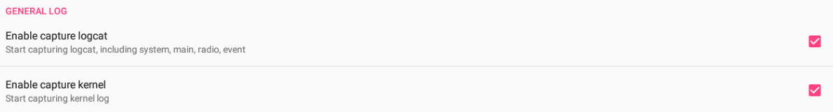
In Debugger, the logcat logs and kernel logs have been separated, if you need "Enable capture logcat" and "Enable capture kernel", make sure those toggles are checked.

-
To enable tcpdump log for debugging internet related issue, make sure "Enable tcpdump" toggle is checked.

-
-
Collecting Logs:
-
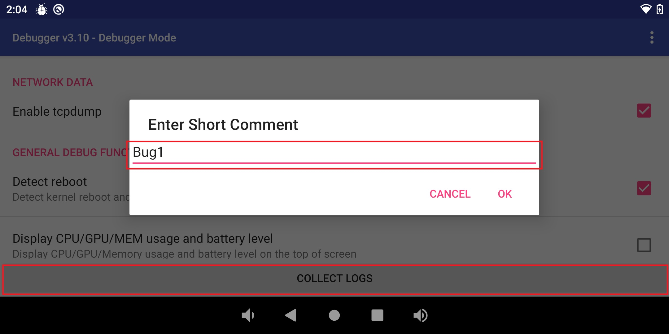
When a bug is found, please press "COLLECT LOGS" button in AsusDebugger. You can describe your findings with short log or simply leave it blank.

-
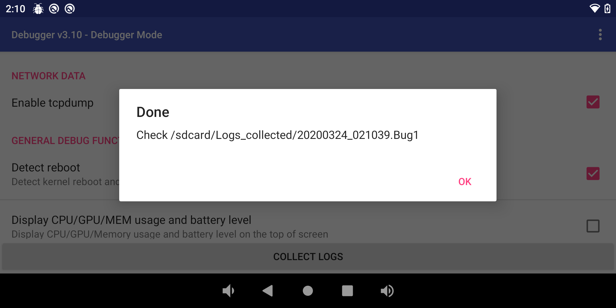
AsusDebugger runs dumpstate automatically when you request collecting logs and it will take some time (2~3 minutes) to generate current system state and information.

Moreover, AsusDebugger collect logs you captured. Once collecting procedure is done, a dialog will be prompted to inform you of the path of the collected logs as follow.

-
-
Output Debugger files:
-
After connecting device to computer, drag the status bar and press "USB drive".

-
Log files in /sdcard/logs are logs for current capture session.
-
All collected logs go to /sdcard/Logs_collected/ directory
-
Copy collected log to USB drive
-
-
Quickly enter AsusDebugger:
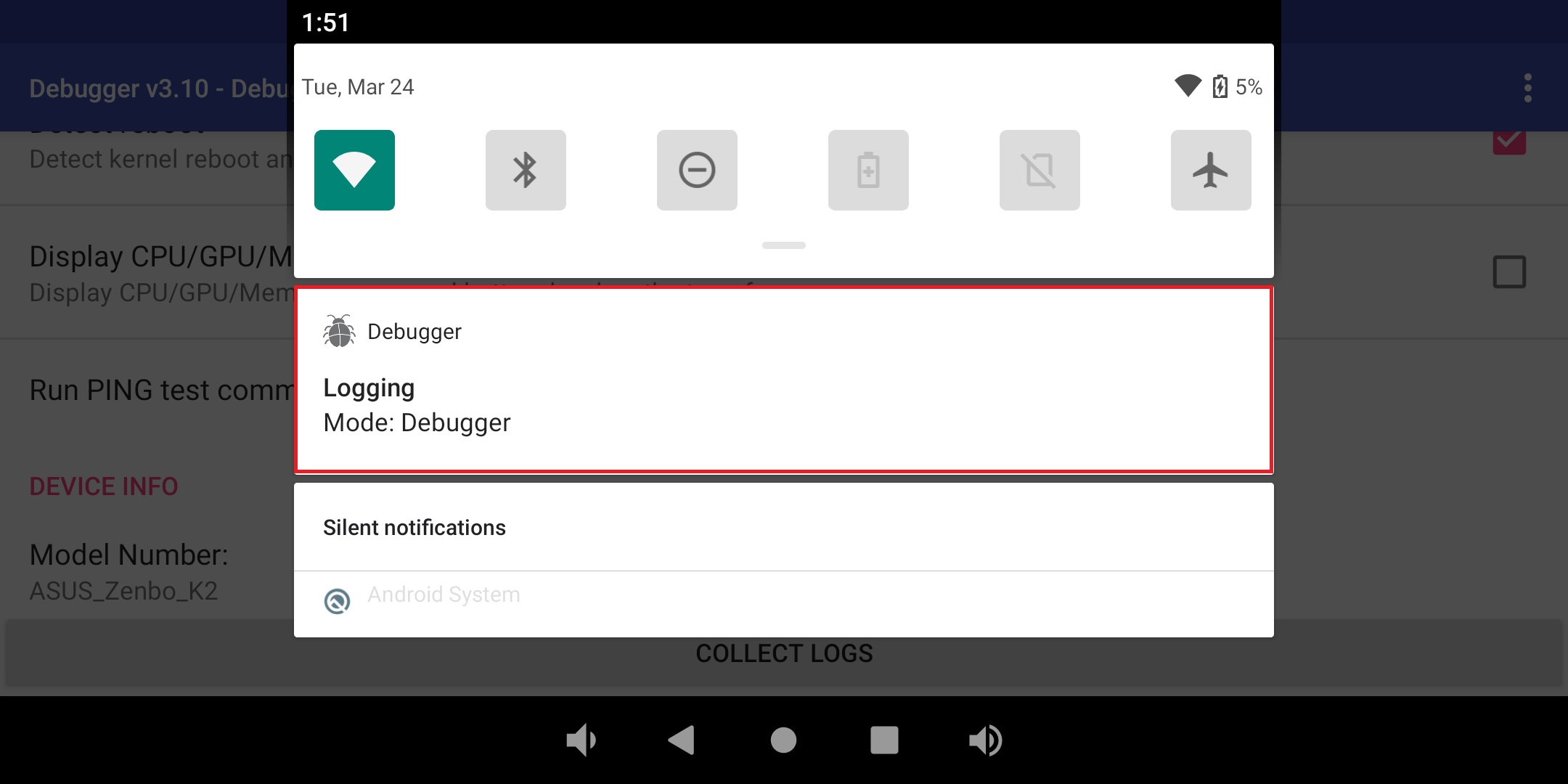
In Section 3 - "Start to catch logs", if any log toggles are enabled, you can see a notification shown the Logging mode is Debugger. You can quickly get into AsusDebugger activity by clicking.

-
Other function:
-
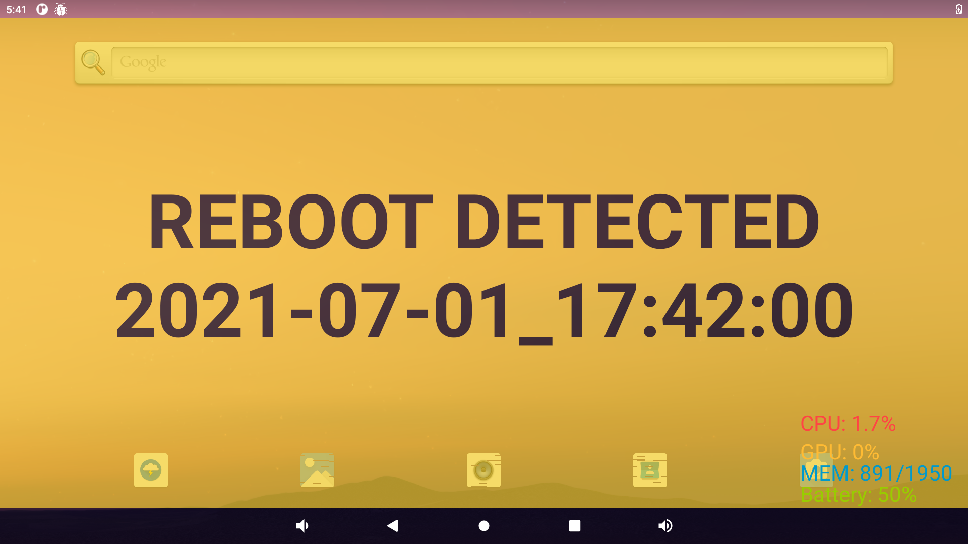
Detect reboot
If you want to detect whether the device is rebooted, make sure "Detect reboot" toggle is checked.

If detect the device is rebooted, there is a full-screen floating window shown and display timestamp. Remove window by clicking it.

-
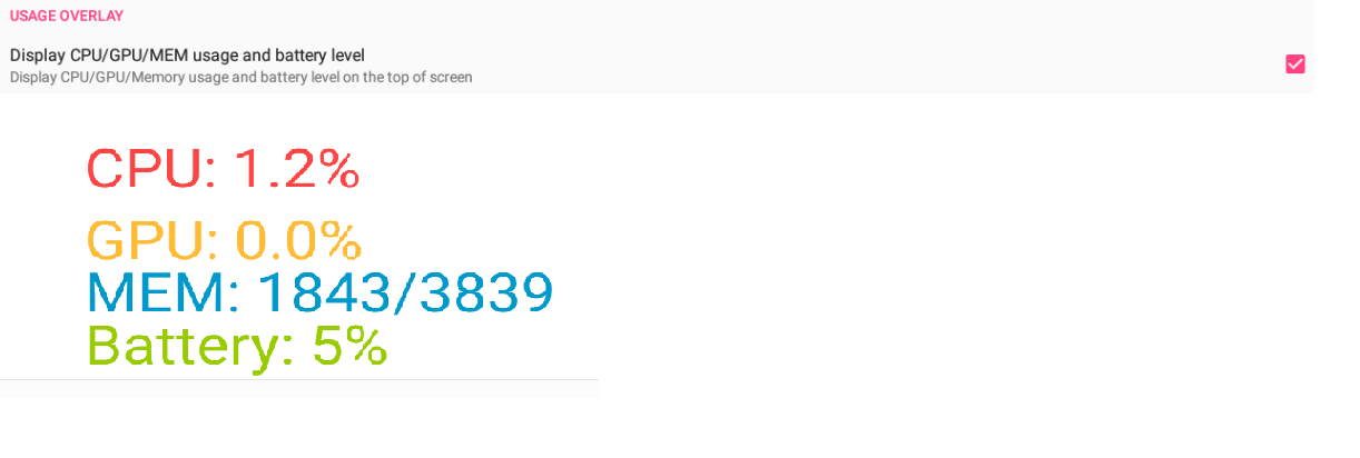
Display usage
If you want to know the device’s usage, includes the information of CPU, GPU, Memory, and Battery, make sure "Display CPU/GPU/MEM usage and battery level" toggle is checked. A floating window displays information at right-bottom corner.

NOTE: GPU usage cannot be shown on Tinker Board.
-
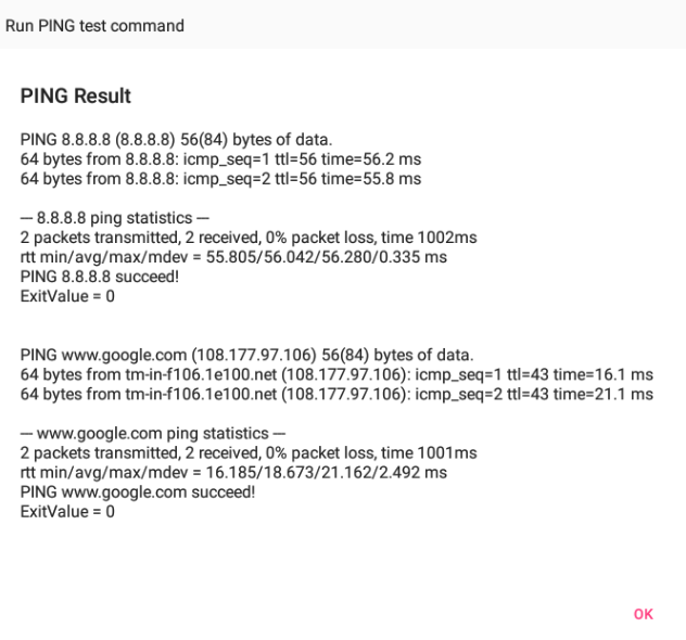
Ping test
If you want to test the network connection, can use "Run PING test command" to run ping test

-
- For Tinker Board 2 / Tinker Board 2S
- This instruction describes behaviors with the version AsusDebugger v3.10
-
Start AsusDebugger:
You CAN’T find AsusDebugger icon in Launcher. Please get into it from "Settings" Application
-
In Launcher, you can find the Settings icon. Click it to start Settings.
-
Click "About tablet" at the bottom of the preference list.

-
Click the “Android Version” preference.

-
Continuously click the preference of “Build number” 10 times and will start open the AsusDebugger.

NOTE: There is a quick way. Please see Section 6.
-
-
Set the configuration of logs:
-
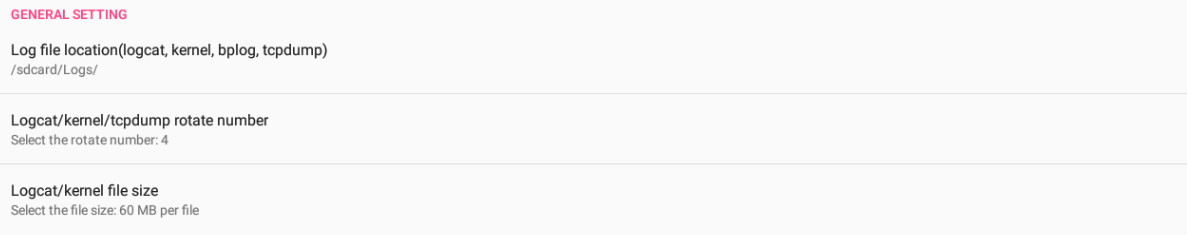
The path of capturing logs is shown at "Log file location", it is default set to "/sdcard/Logs".
-
"Logcat/kernel/tcpdump rotate number" is used to decide the number of log rotation. It affects logcat, kernel, and tcpdump.
-
"Logcat/kernel file size" is used to decide the size of log files. It affects logcat, and kernel.

-
-
Start to catch logs:
-
In Debugger, the logcat logs and kernel logs have been separated, if you need "Enable capture logcat" and "Enable capture kernel", make sure those toggles are checked.
-
To enable tcpdump log for debugging internet related issue, make sure "Enable tcpdump" toggle is checked.

-
-
Collecting Logs:
-
When a bug is found, please press "COLLECT LOGS" button in AsusDebugger. You can describe your findings with short log or simply leave it blank.

-
AsusDebugger runs dumpstate automatically when you request collecting logs and it will take some time (2~3 minutes) to generate current system state and information.

Moreover, AsusDebugger collect logs you captured. Once collecting procedure is done, a dialog will be prompted to inform you of the path of the collected logs as follow.

-
-
Output Debugger files:
-
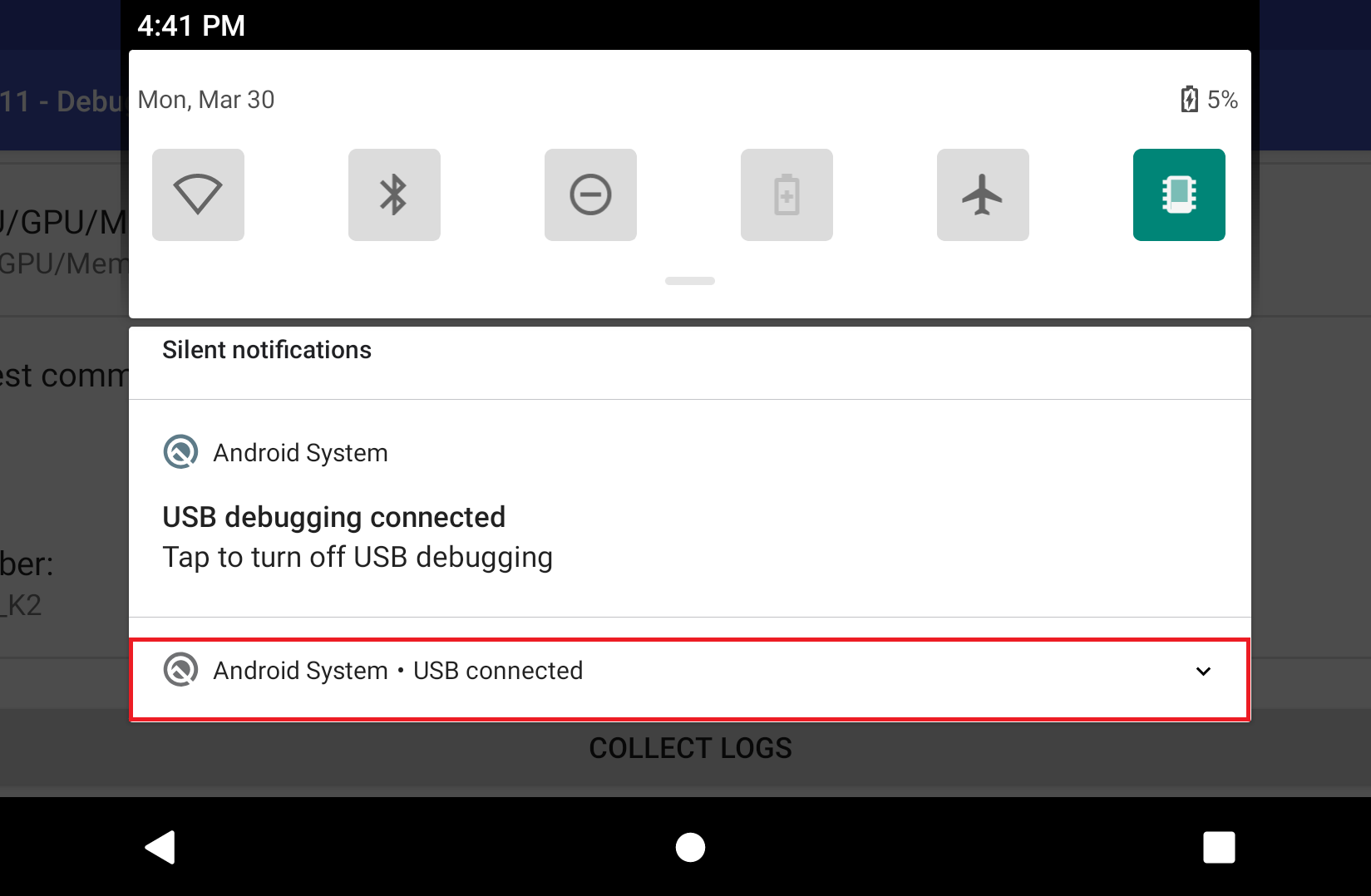
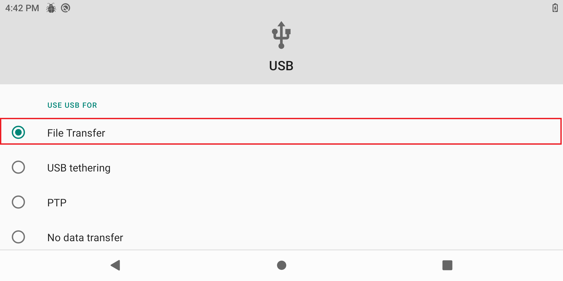
After connecting device to computer, drag the status bar and press "USB connected". Then select "File Transfer".


-
Log files in /sdcard/logs are logs for current capture session.
-
All collected logs go to /sdcard/Logs_collected/ directory
-
-
Quickly enter AsusDebugger:
In Section 3 - "Start to catch logs", if any log toggles are enabled, you can see a notification shown the Logging mode is Debugger. You can quickly get into AsusDebugger activity by clicking.
-
Other function:
-
Detect reboot:
If you want to detect whether the device is rebooted, make sure "Detect reboot" toggle is checked.

If detect the device is rebooted, there is a full-screen floating window shown and display timestamp. Remove window by clicking it.

-
Display usage:
If you want to know the device’s usage, includes the information of CPU, GPU, Memory, and Battery, make sure "Display CPU/GPU/MEM usage and battery level" toggle is checked. A floating window displays information at right-bottom corner.

-
Ping test:
If you want to test the network connection, can use "Run PING test command" to run ping test


-
- For Tinker Board R2.0 / Tinker Board S R2.0 / Tinker Board 2 / Tinker Board 2S
- This instruction describes behaviors with the version AsusDebugger v3.11
-
Start AsusDebugger:
You CAN’T find AsusDebugger icon in Launcher. Please get into it from "Settings" Application
-
In Launcher, you can find the Settings icon. Click it to start Settings.
-
Click "About tablet" at the bottom of the preference list.
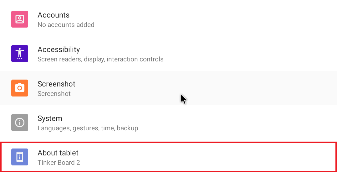
-
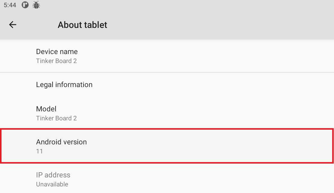
Click “Android Version” preference.
-
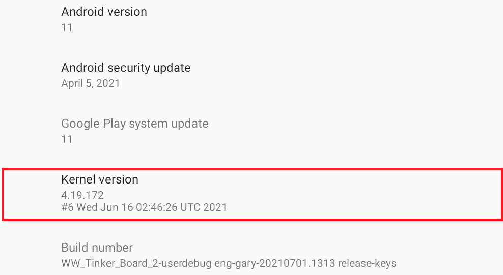
Continuously click “Kernel version“ preference 10 times and the AsusDebugger will start.
NOTE: There is a quick way. Please see Section 6.
-
-
Set the configuration of logs:
-
The path of capturing logs is shown at "Log file location", it is default set to "/sdcard/Logs".
-
"Logcat/kernel/tcpdump rotate number" is used to decide the number of log rotation. It affects logcat, kernel, and tcpdump.
-
"Logcat/kernel file size" is used to decide the size of log files. It affects logcat, and kernel.
-
-
Start to catch logs:
-
In Debugger, the logcat logs and kernel logs have been separated, if you need "Enable capture logcat" and "Enable capture kernel", make sure those toggles are checked.
-
To enable tcpdump log for debugging internet related issue, make sure "Enable tcpdump" toggle is checked.

-
-
Collecting Logs:
-
When a bug is found, please press "COLLECT LOGS" button in AsusDebugger. You can describe your findings with short log or simply leave it blank.
-
AsusDebugger runs dumpstate automatically when you request collecting logs and it will take some time (1~2 minutes) to generate current system state and information.

Moreover, AsusDebugger collect logs you captured. Once collecting procedure is done, a dialog will be prompted to inform you of the path of the collected logs as follows.
-
-
Output Debugger files:
-
After connecting device to computer, drag the status bar and press "USB connected". Then select "File transfers".
-
Log files in /sdcard/logs are logs for current capture session.
-
All collected logs go to /sdcard/Logs_collected/ directory
-
-
Quickly enter AsusDebugger:
In Section 3 - "Start to catch logs", if any log toggles are enabled, you can see a notification shown the Logging mode is Debugger. You can quickly get into AsusDebugger activity by clicking.
-
Other function:
-
Detect reboot:
If you want to detect whether the device is rebooted, make sure "Detect reboot" toggle is checked.

If detect the device is rebooted, there is a full-screen floating window shown and display timestamp. Remove window by clicking it.
-
Display usage:
If you want to know the device’s usage, includes the information of CPU, Memory, and Battery, make sure "Display CPU/GPU/MEM usage and battery level" toggle is checked. A floating window displays information at right-bottom corner.
-
Ping test:
If you want to test the network connection, can use "Run PING test command" to run ping test.
-
-
For Tinker Board / Tinker Board S / Tinker Board R2.0 / Tinker Board S R2.0
-
CPU (A17) Governor setting is in
/sys/devices/system/cpu/cpufreq/policy0/scaling_governoruse 'echo' to change.
EX:echo ondemand > /sys/devices/system/cpu/cpufreq/policy0/scaling_governorCPU minimum frequency: /sys/devices/system/cpu/cpufreq/policy0/scaling_min_freq CPU maximum frequency: /sys/devices/system/cpu/cpufreq/policy0/scaling_max_freqNote: Check available parameter for CPU (A17) in
/sys/devices/system/cpu/cpufreq/policy0before setting. -
GPU (T76X) Governor setting:
/sys/class/devfreq/ffa30000.gpu/governorGPU minimum frequency: /sys/class/devfreq/ffa30000.gpu/min_freq GPU maximum frequency: /sys/class/devfreq/ffa30000.gpu/max_freqNote: Check available parameter for GPU (T76X) in
/sys/class/devfreq/ffa30000.gpubefore setting.
-
-
For Tinker Board 2 / Tinker Board 2S
-
CPU (A53) Governor setting is in
/sys/devices/system/cpu/cpufreq/policy0/scaling_governoruse 'echo' to change.
EX:echo ondemand > /sys/devices/system/cpu/cpufreq/policy0/scaling_governorCPU(A53) minimum frequency: /sys/devices/system/cpu/cpufreq/policy0/scaling_min_freq CPU(A53) maximum frequency: /sys/devices/system/cpu/cpufreq/policy0/scaling_max_freqNote: Check available parameter for CPU (A53) in
/sys/devices/system/cpu/cpufreq/policy0before setting.CPU(A72) Governor setting: /sys/devices/system/cpu/cpufreq/policy4/scaling_governor CPU(A72) minimum frequency: /sys/devices/system/cpu/cpufreq/policy4/scaling_min_freq CPU(A72) maximum frequency: /sys/devices/system/cpu/cpufreq/policy4/scaling_max_freqNote: Check available parameter for CPU (A72) in
/sys/devices/system/cpu/cpufreq/policy4before setting. -
GPU (T86X) Governor setting:
/sys/class/devfreq/ff9a0000.gpu/governorGPU minimum frequency: /sys/class/devfreq/ff9a0000.gpu/min_freq GPU maximum frequency: /sys/class/devfreq/ff9a0000.gpu/max_freqNote: Note: Check available parameter for GPU (T86X) in
/sys/class/devfreq/ff9a0000.gpubefore setting.
-
-
For Tinker Board / Tinker Board S / Tinker Board R2.0 / Tinker Board S R2.0
-
Download
-
Kernel Code
$ git clone https://github.com/TinkerBoard/debian_kernel.git -
GCC
$ wget http://releases.linaro.org/components/toolchain/binaries/6.3-2017.05/aarch64-linux-gnu/gcc-linaro-6.3.1-2017.05-x86_64_aarch64-linux-gnu.tar.xz
$ tar Jxvf gcc-linaro-6.3.1-2017.05-x86_64_aarch64-linux-gnu.tar.xz -C ~
Tinker Board logo:
/kernel/logo.bmp -
-
Execute instructions as follows on PC
$ git clone https://github.com/TinkerBoard/debian_kernel.git $ cd debian_kernel $ git checkout -b tinker_board-debian-3.0.11 $ cd debian_kernel $ make ARCH=arm tinker_board_defconfig $ make ARCH=arm CROSS_COMPILE=~/gcc-linaro-6.3.1-2017.05-x86_64_arm-linux-gnueabihf/bin/arm-linux-gnueabihf- rk3288-tinker_board.img -j48 $ make ARCH=arm CROSS_COMPILE=~/gcc-linaro-6.3.1-2017.05-x86_64_arm-linux-gnueabihf/bin/arm-linux-gnueabihf- rk3288-tinker_board.img modules -j48 -
When compilation has finished, copy "debian-kernel/zboot.img" to the tinker board
$ sudo dd if=zboot.img of=/dev/mmcblk1p4
$ sudo reboot
-
For Tinker Board 2 / Tinker Board 2S
-
Method 1:
-
Convert the logo file to 24 bit BMP file. It is recommended to use Window Paint for conversion.
Note: After converting to 24 bit BMP file, the BMP file MUST less than 700K bytes.
-
Rename the BMP file to logo.bmp
-
Copy logo.bmp and rename it to logo_kernel.bmp
-
Replace logo.bmp and logo_kernel.bmp with logo.bmp and logo_kernel.bmp under sourcecode/kernel.
-
Build kernel image and flash kernel image.
- Method 2:
-
Convert the logo file to 24 bit BMP file. It is recommended to use Window Paint for conversion
Note: After converting to 24 bit BMP file, the BMP file MUST less than 700K bytes.
-
Rename the BMP file to logo.bmp
-
Copy logo.bmp to sourcecode/kernel/scripts/
-
Execute the following command on the ubuntu server:
./bmpconvert logo.bmp -
You will see the following message after the command is successful

-
Powering on device, and open terminal.
Enter “reboot-bootloader” in terminal to enter fastboot mode
-
Execute command to flash logo.bmp into splash partition
fastboot flash splash logo.bmp
-
For Tinker Board / Tinker Board S
-
For Android M/N
-
Static boot logo
-
Requirement
-
Please prepare the 24 bit bmp file and the length/width must be divisible by 4.
- For example : 1000x400, 1920x1080 are OK, but 1921x1000 is not allowed
- We recommended that you can use the Microsoft paint to save the picture as the 24 bit bmp.
- Let's assume the picture name is logo.bmp
-
Use the linux tool "convert" to change the format
$ convert -compress rle -colors 256 logo.bmp logo_kernel.bmplogo.bmp is the file which is came from step 1 and logo_kernel.bmp is the file which is after convert.
-
Android M: Replace the logo.bmp and logo_kernel.bmp which is came from step 1 and step 2 to the kernel folder
Android N: Use the logo_kernel.bmp which is came from step 2 to replace the logo.bmp and logo_kernel.bmp at kernel folder -
Rebuild kernel image: How to rebuild kernel
-
-
Note:
-
Please notice that the version of "convert" is also importance. The version of convert must be equal to the below
$ convert -version Version: ImageMagick 6.6.9-7 2017-03-14 Q16 http://www.imagemagick.org Copyright: Copyright (C) 1999-2011 ImageMagick Studio LLC Features: OpenMP -
If your OS is Ubuntu 12.04,just use apt to get the convert package
$ sudo apt-get install imagemagick -
If you have no Ubuntu 12.04, you can use the Tinker Board with Tinker-OS V2.0.3
$ sudo apt-get install graphicsmagick-imagemagick-compat
-
-
-
Dynamic boot logo
You can reference the bootanimation.zip and replaced the png file inside. The Android framework will play the picture from 0.png to the last png file one by one. And it will look like an animation.
After you finish the zip file, please put the bootanimation.zip to/system/media/bootanimation.zip
The zip file name must be bootanimation.zip. You can download the example from below link
https://bitbucket.org/TinkerBoard_Android/rk-device-rockchip-rk3288/raw/e57382fe021e651a01d3b3f6b3df21a6f5ed19d1/rk3288_vr/bootanimation.zip -
Wallpaper
Please check the following 2 commits. One is for HDMI and the other is for DSI.
https://bitbucket.org/TinkerBoard_Android/rk-device-rockchip-rk3288/commits/a5a00b724063b3992a1e6ad711e69e0f4ecd63ce?at=sbc/tinkerboard/asus/Android-6.0.1
https://bitbucket.org/TinkerBoard_Android/rk-device-rockchip-rk3288/commits/0a382ad572b909d758553c43a6b6c929aacbadc6?at=sbc/tinkerboard/asus/Android-6.0.1
- For Tinker Board 2 / Tinker Board 2S
-
Download and Install Tinker Config App
Download the apk file Tinker Config App and use the following command to install app
$ adb install TinkerConfig_1.0.2_20220210.apk -
Launch Tinker Config App

-
Press “Boot Logo” button.

-
Press “Change Image” button.

-
Select the image you want to set, and press “Apply” button.

-
Reboot the device, and you can get your own boot logo.
This instruction is applicable for Tinker Board and Tinker Board 2 with Android 11 OS
-
Requirements
-
adb connection
- For Tinker Board 2 / Tinker Board 2S: USB Type-C cable or WIFI available
- For Tinker Board / Tinker Board S / Tinker Board R2.0 / Tinker Board S R2.0: WIFI available
-
bootanimation.zip file
- You can create a bootanimation.zip by yourself or download it from the Internet.
-
-
Connect Tinker Board 2 to PC with USB Type-C cable or connect to the device over WIFI as bellow
$ adb connect <Tinker IP address> -
Push bootanimation.zip to Tinker Board 2 / Tinker Board 2S
$ adb root $ adb remount $ adb push bootanimation.zip product/media/bootanimation.zip $ adb reboot -
After reboot, you can get your own Android boot animation.
Tinker Board and Tinker Board S:
- The IO mapping can be found at:
https://github.com/TinkerBoard/TinkerBoard/wiki/User-Guide#gpio-config-table-for-tinker-board-and-tinker-board-s
Tinker Board 2S:
- The IO mapping can be found at:
https://github.com/TinkerBoard/TinkerBoard/wiki/User-Guide#gpio-config-table-for-tinker-board-2s
I2C WiringPi for C library for Debian
- Firstly, modify the /boot/config.txt file as following and then reboot to enable I2C1 and I2C4.
##### Hardware Interface Config #######
Note: fiq_debugger and uart3 use the same pin. Set fiq_debugger first while bb oth on. ##
## Note: uart4 and spi0 are the same pins. Set the latter one while both on. ##
## Note: uart2 is the same pins to pwm2 and pwm3. Set the latter one while both on. ##

intf:fiq_debugger=on
intf:i2c1=on
intf:i2c4=on
#intf:spi0=off
#intf:spi2=off
#intf:pwm2=off
#intf:pwm3=off
intf:pcm_i2s=on
#intf:uart1=off
#intf:uart2=off
#intf:uart3=off
#intf:uart4=off
- Compiler the following sample codes for DS3231 RTC device
1. Sample codes ds3231.c
==============================================================
#include <wiringPi.h>
#include <wiringPiI2C.h>
#include <stdio.h>

#define DS3231_Address 0x68
//seconds,minutes,hours,weekdays,days,months,yeas
char  buf[]={0x00,0x00,0x22,0x06,0x27,0x12,0x19};
char  *str[]  ={"SUN","Mon","Tues","Wed","Thur","Fri","Sat"};
int fd,i;

void pcf8563SetTime()
{
    for(i = 0;i < 7;i++)
    {
        wiringPiI2CWriteReg8(fd,i,buf[i]);
    }
}

void pcf8563ReadTime()
{
    for(i = 0;i < 7;i++)
    {
        buf[i] = (char)wiringPiI2CReadReg8(fd,i);
    }
}

int main(int argc, char **argv)
{
    if(wiringPiSetup() < 0)return 1;
       fd = wiringPiI2CSetup(DS3231_Address);
    printf("DS3231 Test Program ...\n\n");

    pcf8563SetTime();
    while(1)
    {
           pcf8563ReadTime();
        buf[0] = buf[0]&0x7F; //sec
        buf[1] = buf[1]&0x7F; //min
        buf[2] = buf[2]&0x3F; //hour
        buf[3] = buf[3]&0x07; //week
        buf[4] = buf[4]&0x3F; //day
        buf[5] = buf[5]&0x1F; //mouth
        //year/month/day
        printf("20%02x/%02x/%02x  ",buf[6],buf[5],buf[4]);
        //hour:minute/second
        printf("%02x:%02x:%02x  ",buf[2],buf[1],buf[0]);
        //weekday
        printf("%s\n",str[(unsigned char)buf[3]]);
        delay(1000);
    }
    return 0;
}
==============================================================
1. Compiler sample code by wiringPi library and then get the ds3231 binary file
   $ gcc -o ds3231 ds3231.c -lwiringPi -DTINKER_BOARD
2. Execute the ds3231 file to get the RTC time
   $ ./ds3231
Reference for the wiringPi API: http://wiringpi.com/reference/i2c-library/
Pwm wiringPi for C library:
- Firstly, modify the /boot/config.txt file as following and then reboot to enable PWM2 and PWM3.
##### Hardware Interface Config #######
Note: fiq_debugger and uart3 use the same pin. Set fiq_debugger first while bb oth on. ##
## Note: uart4 and spi0 are the same pins. Set the latter one while both on. ##
## Note: uart2 is the same pins to pwm2 and pwm3. Set the latter one while both on. ##

intf:fiq_debugger=on
#intf:i2c1=off
#intf:i2c4=off
#intf:spi0=off
#intf:spi2=off
intf:pwm2=on
intf:pwm3=on
intf:pcm_i2s=on
#intf:uart1=off
#intf:uart2=off
#intf:uart3=off
#intf:uart4=off
- Compiler the following sample codes for SPI interface
1. Sample codes : gpio_lib_c/examples/pwm.c
#include <wiringPi.h>

#include <stdio.h>
#include <stdlib.h>
#include <stdint.h>

int main (void)
{
  int bright ;

  printf ("Raspberry Pi wiringPi PWM test program\n") ;
  wiringPiSetup();
  pinMode (26, PWM_OUTPUT) ;
  for (;;)
  {
    for (bright = 0 ; bright < 1024 ; bright=bright+4)
    {
      pwmWrite (26, bright) ;
      delay (10) ;
    }

    for (bright = 1023 ; bright >= 0 ; bright=bright-4)
    {
      pwmWrite (26, bright) ;
      delay (10) ;
    }
  }

  return 0 ;
}
1. Compiler sample code by wiringPi library and then get the softPwm binary file
   $ gcc -o pwm pwm.c -lwiringPi -DTINKER_BOARD
2. Execute the pwm binary file to show led blinking.
   $ ./pwm
Spi wiringPi for C library:
- Firstly, modify the /boot/config.txt file as following and then reboot to enable SPI0 and SPI2.
##### Hardware Interface Config #######
Note: fiq_debugger and uart3 use the same pin. Set fiq_debugger first while bb oth on. ##
## Note: uart4 and spi0 are the same pins. Set the latter one while both on. ##
## Note: uart2 is the same pins to pwm2 and pwm3. Set the latter one while both on. ##

intf:fiq_debugger=on
#intf:i2c1=off
#intf:i2c4=off
intf:spi0=on
intf:spi2=on
#intf:pwm2=off
#intf:pwm3=off
intf:pcm_i2s=on
#intf:uart1=off
#intf:uart2=off
#intf:uart3=off
#intf:uart4=off
- Compiler the following sample codes for SPI interface
1. Sample codes gpio_lib_c/examples/spiSpeed.c
==============================================================
/*
* spiSpeed.c:
* Code to measure the SPI speed/latency.
* Copyright (c) 2014 Gordon Henderson
***********************************************************************
* This file is part of wiringPi:
* https://projects.drogon.net/raspberry-pi/wiringpi/
*
* wiringPi is free software: you can redistribute it and/or modify
* it under the terms of the GNU Lesser General Public License as
* published by the Free Software Foundation, either version 3 of the
* License, or (at your option) any later version.
*
* wiringPi is distributed in the hope that it will be useful,
* but WITHOUT ANY WARRANTY; without even the implied warranty of
* MERCHANTABILITY or FITNESS FOR A PARTICULAR PURPOSE. See the
* GNU Lesser General Public License for more details.
*
* You should have received a copy of the GNU Lesser General Public
* License along with wiringPi.
* If not, see <http://www.gnu.org/licenses/>.
***********************************************************************
*/
#include <stdio.h>
#include <stdlib.h>
#include <unistd.h>
#include <stdint.h>
#include <string.h>
#include <errno.h>
#include <wiringPi.h>
#include <wiringPiSPI.h>
#define TRUE (1==1)
#define FALSE (!TRUE)
#define SPI_CHAN 0
#define NUM_TIMES 100
#define MAX_SIZE (1024*1024)
static int myFd ;
void spiSetup (int speed)
{
if ((myFd = wiringPiSPISetup (SPI_CHAN, speed)) < 0)
{
fprintf (stderr, "Can't open the SPI bus: %s\n", strerror (errno)) ;
exit (EXIT_FAILURE) ;
}
}
int main (void)
{
int speed, times, size ;
unsigned int start, end ;
int spiFail ;
unsigned char *myData ;
double timePerTransaction, perfectTimePerTransaction, dataSpeed ;
if ((myData = malloc (MAX_SIZE)) == NULL)
{
fprintf (stderr, "Unable to allocate buffer: %s\n", strerror (errno)) ;
exit (EXIT_FAILURE) ;
}
wiringPiSetup () ;
for (speed = 1 ; speed <= 32 ; speed *= 2)
{
printf ("+-------+--------+----------+----------+-----------+------------+\n") ;
printf ("| MHz | Size | mS/Trans | TpS | Mb/Sec | Latency mS |\n") ;
printf ("+-------+--------+----------+----------+-----------+------------+\n") ;
spiFail = FALSE ;
spiSetup (speed * 1000000) ;
for (size = 1 ; size <= MAX_SIZE ; size *= 2)
{
printf ("| %5d | %6d ", speed, size) ;
start = millis () ;
for (times = 0 ; times < NUM_TIMES ; ++times)
if (wiringPiSPIDataRW (SPI_CHAN, myData, size) == -1)
{
printf ("SPI failure: %s\n", strerror (errno)) ;
spiFail = TRUE ;
break ;
}
end = millis () ;
if (spiFail)
break ;
timePerTransaction = ((double)(end - start) / (double)NUM_TIMES) / 1000.0 ;
dataSpeed = (double)(size * 8) / (1024.0 * 1024.0) / timePerTransaction ;
perfectTimePerTransaction = ((double)(size * 8)) / ((double)(speed * 1000000)) ;
printf ("| %8.3f ", timePerTransaction * 1000.0) ;
printf ("| %8.1f ", 1.0 / timePerTransaction) ;
printf ("| %9.5f ", dataSpeed) ;
printf ("| %8.5f ", (timePerTransaction - perfectTimePerTransaction) * 1000.0) ;
printf ("|\n") ;
}
close (myFd) ;
printf ("+-------+--------+----------+----------+-----------+------------+\n") ;
printf ("\n") ;
}
return 0 ;
}
==============================================================
1. Compiler sample code by wiringPi library and then get the piSpeed binary file
   $ gcc -o spiSpeed spiSpeed.c -lwiringPi -DTINKER_BOARD
2. Execute the spiSpeed file to get the RTC time
   $ sudo ./spiSpeed
+-------+--------+----------+----------+-----------+------------+
|   MHz |   Size | mS/Trans |      TpS |    Mb/Sec | Latency mS |
+-------+--------+----------+----------+-----------+------------+
|     1 |      1 |    0.010 | 100000.0 |   0.76294 |    0.00200 |
|     1 |      2 |    0.030 |  33333.3 |   0.50863 |    0.01400 |
|     1 |      4 |    0.040 |  25000.0 |   0.76294 |    0.00800 |
|     1 |      8 |    0.070 |  14285.7 |   0.87193 |    0.00600 |
|     1 |     16 |    0.140 |   7142.9 |   0.87193 |    0.01200 |
|     1 |     32 |    0.270 |   3703.7 |   0.90422 |    0.01400 |
|     1 |     64 |    0.570 |   1754.4 |   0.85663 |    0.05800 |
|     1 |    128 |    1.130 |    885.0 |   0.86421 |    0.10600 |
|     1 |    256 |    2.250 |    444.4 |   0.86806 |    0.20200 |
|     1 |    512 |    4.480 |    223.2 |   0.87193 |    0.38400 |
|     1 |   1024 |    8.400 |    119.0 |   0.93006 |    0.20800 |
|     1 |   2048 |   16.950 |     59.0 |   0.92183 |    0.56600 |
|     1 |   4096 |   33.370 |     30.0 |   0.93647 |    0.60200 |
|     1 |   8192 SPI failure: Message too long
+-------+--------+----------+----------+-----------+------------+

+-------+--------+----------+----------+-----------+------------+
|   MHz |   Size | mS/Trans |      TpS |    Mb/Sec | Latency mS |
+-------+--------+----------+----------+-----------+------------+
|     2 |      1 |    0.100 |  10000.0 |   0.07629 |    0.09600 |
|     2 |      2 |    0.110 |   9090.9 |   0.13872 |    0.10200 |
|     2 |      4 |    0.150 |   6666.7 |   0.20345 |    0.13400 |
|     2 |      8 |    0.110 |   9090.9 |   0.55487 |    0.07800 |
|     2 |     16 |    0.110 |   9090.9 |   1.10973 |    0.04600 |
|     2 |     32 |    0.310 |   3225.8 |   0.78755 |    0.18200 |
|     2 |     64 |    0.380 |   2631.6 |   1.28495 |    0.12400 |
|     2 |    128 |    0.580 |   1724.1 |   1.68373 |    0.06800 |
|     2 |    256 |    1.130 |    885.0 |   1.72843 |    0.10600 |
|     2 |    512 |    2.260 |    442.5 |   1.72843 |    0.21200 |
....
Reference for the wiringPi API: http://wiringpi.com/reference/spi-library/
Uart wiringPi for C library:
- Firstly, modify the /boot/config.txt file as following and then reboot to enable UART1, UART2 and UART4.
##### Hardware Interface Config #######
Note: fiq_debugger and uart3 use the same pin. Set fiq_debugger first while bb oth on. ##
## Note: uart4 and spi0 are the same pins. Set the latter one while both on. ##
## Note: uart2 is the same pins to pwm2 and pwm3. Set the latter one while both on. ##

intf:fiq_debugger=on
#intf:i2c1=off
#intf:i2c4=off
#intf:spi0=off
#intf:spi2=off
#intf:pwm2=off
#intf:pwm3=off
intf:pcm_i2s=on
intf:uart1=on
intf:uart2=on
#intf:uart3=off
intf:uart4=on
- Compiler the following sample codes by Uart cable
1. Test the Uart1 TX/RX by Sample codes gpio_lib_c/examples/serialTest.c
==============================================================
/*
 * serialTest.c:
 *	Very simple program to test the serial port. Expects
 *	the port to be looped back to itself
 *
 * Copyright (c) 2012-2013 Gordon Henderson.
 ***********************************************************************
 * This file is part of wiringPi:
 *	https://projects.drogon.net/raspberry-pi/wiringpi/
 *
 *    wiringPi is free software: you can redistribute it and/or modify
 *    it under the terms of the GNU Lesser General Public License as published by
 *    the Free Software Foundation, either version 3 of the License, or
 *    (at your option) any later version.
 *
 *    wiringPi is distributed in the hope that it will be useful,
 *    but WITHOUT ANY WARRANTY; without even the implied warranty of
 *    MERCHANTABILITY or FITNESS FOR A PARTICULAR PURPOSE.  See the
 *    GNU Lesser General Public License for more details.
 *
 *    You should have received a copy of the GNU Lesser General Public License
 *    along with wiringPi.  If not, see .
 ***********************************************************************
 */

#include <stdio.h>
#include <string.h>
#include <errno.h>

#include <wiringPi.h>
#include <wiringSerial.h>

int main ()
{
  int fd ;
  int count ;
  unsigned int nextTime ;

  if ((fd = serialOpen ("/dev/ttyS1", 115200)) < 0)
  {
    fprintf (stderr, "Unable to open serial device: %s\n", strerror (errno)) ;
    return 1 ;
  }

  if (wiringPiSetup () == -1)
  {
    fprintf (stdout, "Unable to start wiringPi: %s\n", strerror (errno)) ;
    return 1 ;
  }

  nextTime = millis () + 300 ;

  for (count = 0 ; count < 256 ; )
  {
    if (millis () > nextTime)
    {
      printf ("\nOut: %3d: ", count) ;
      fflush (stdout) ;
      serialPutchar (fd, count) ;
      nextTime += 300 ;
      ++count ;
    }

    delay (3) ;

    while (serialDataAvail (fd))
    {
      printf (" -> %3d", serialGetchar (fd)) ;
      fflush (stdout) ;
    }
  }

  printf ("\n") ;
  return 0 ;
}

==============================================================
1. Compiler sample code by wiringPi library and then get the serialTest binary file
   $ gcc -o serialTest serialTest.c -lwiringPi -DTINKER_BOARD
2. Execute the serialTest file to test Uart TX/RX
   $ ./serialTest
   -> Device log for RX
      ...
      "Out:  17:  ->  80 -> 117 -> 84 -> 84 -> 89"
      "Out:  18:"
      ...
   -> PC putty log for TX
      "...!"#$%&'()*+,-./0123456789:;<=>?@ABCDEFGHIJKLMNOPQRSTUVWXYZ[\]^_`abcdefghijklmnopqrstuvwxyz{|}..."
Reference for the wiringPi API: http://wiringpi.com/reference/serial-library/
I2C WiringPi for C library for Debian
- Firstly, modify the /boot/config.txt file as following and then reboot to enable I2C6 (wiringPi only support 1 I2C interface).
##### Hardware Interface Config #####

## Note: uart4 and spi1 are the same pins. Set the latter one while both on. ##

intf:fiq_debugger=on
#intf:uart0=off
#intf:uart4=off
intf:i2c6=on
#intf:i2c7=off
#intf:i2s0=off
#intf:spdif=off
#intf:spi1=off
#intf:spi5=off
#intf:pwm0=off
#intf:pwm1=off
#intf:pwm3a=off
#intf:test_clkout2=off
- Compiler the following sample codes for DS3231 RTC device
1. Sample codes ds3231.c
==============================================================
#include <wiringPi.h>
#include <wiringPiI2C.h>
#include <stdio.h>

#define DS3231_Address 0x68
//seconds,minutes,hours,weekdays,days,months,yeas
char  buf[]={0x00,0x00,0x22,0x06,0x27,0x12,0x19};
char  *str[]  ={"SUN","Mon","Tues","Wed","Thur","Fri","Sat"};
int fd,i;

void pcf8563SetTime()
{
    for(i = 0;i < 7;i++)
    {
        wiringPiI2CWriteReg8(fd,i,buf[i]);
    }
}

void pcf8563ReadTime()
{
    for(i = 0;i < 7;i++)
    {
        buf[i] = (char)wiringPiI2CReadReg8(fd,i);
    }
}

int main(int argc, char **argv)
{
    if(wiringPiSetup() < 0)return 1;
       fd = wiringPiI2CSetup(DS3231_Address);
    printf("DS3231 Test Program ...\n\n");

    pcf8563SetTime();
    while(1)
    {
           pcf8563ReadTime();
        buf[0] = buf[0]&0x7F; //sec
        buf[1] = buf[1]&0x7F; //min
        buf[2] = buf[2]&0x3F; //hour
        buf[3] = buf[3]&0x07; //week
        buf[4] = buf[4]&0x3F; //day
        buf[5] = buf[5]&0x1F; //mouth
        //year/month/day
        printf("20%02x/%02x/%02x  ",buf[6],buf[5],buf[4]);
        //hour:minute/second
        printf("%02x:%02x:%02x  ",buf[2],buf[1],buf[0]);
        //weekday
        printf("%s\n",str[(unsigned char)buf[3]]);
        delay(1000);
    }
    return 0;
}
==============================================================
- Compiler sample code by wiringPi library and then get the ds3231 binary file
$ gcc -o ds3231 ds3231.c -lwiringPi
- Execute the ds3231 file to get the RTC time
$ ./ds3231
.C file of ds3231: https://github.com/TinkerBoard/TinkerBoard/files/8108998/ds3231.zip
Reference of the wiringPi API: http://wiringpi.com/reference/i2c-library/
Pwm wiringPi for C library:
- Firstly, modify the /boot/config.txt file as following and then reboot for SoftPwm function.
##### Hardware Interface Config #####

## Note: uart4 and spi1 are the same pins. Set the latter one while both on. ##

intf:fiq_debugger=on
#intf:uart0=off
#intf:uart4=off
#intf:i2c6=off
#intf:i2c7=off
#intf:i2s0=off
#intf:spdif=off
#intf:spi1=off
#intf:spi5=off
#intf:pwm0=off
#intf:pwm1=off
#intf:pwm3a=off
#intf:test_clkout2=off
- Compiler the following sample codes for SPI interface
1. Sample codes /usr/local/share/gpio_lib_c_rk3399/examples/softPwm.c
==============================================================
#include
#include
#include

#include
#include

#define RANGE		100
#define	NUM_LEDS	  8

int ledMap [NUM_LEDS] = { 0, 1, 2, 3, 4, 5, 6, 7 } ;

int values [NUM_LEDS] = { 0, 25, 50, 75, 100, 75, 50, 25 } ;

int main ()
{
  int i, j ;
  char buf [80] ;

  wiringPiSetup ()  ;

  for (i = 0 ; i < NUM_LEDS ; ++i)
  {
    softPwmCreate (ledMap [i], 0, RANGE) ;
    printf ("%3d, %3d, %3d\n", i, ledMap [i], values [i]) ;
  }

  fgets (buf, 80, stdin) ;

// Bring all up one by one:

  for (i = 0 ; i < NUM_LEDS ; ++i)
    for (j = 0 ; j <= 100 ; ++j)
    {
      softPwmWrite (ledMap [i], j) ;
      delay (10) ;
    }

  fgets (buf, 80, stdin) ;

// All Down

  for (i = 100 ; i > 0 ; --i)
  {
    for (j = 0 ; j < NUM_LEDS ; ++j)
      softPwmWrite (ledMap [j], i) ;
    delay (10) ;
  }

  fgets (buf, 80, stdin) ;

  for (;;)
  {
    for (i = 0 ; i < NUM_LEDS ; ++i)
      softPwmWrite (ledMap [i], values [i]) ;

    delay (50) ;

    i = values [0] ;
    for (j = 0 ; j < NUM_LEDS - 1 ; ++j)
      values [j] = values [j + 1] ;
    values [NUM_LEDS - 1] = i ;
  }
}
==============================================================
1. Compiler sample code by wiringPi library and then get the softPwm binary file
   $ gcc -o softPwm softPwm.c -lwiringPi
2. Execute the softPwm file to simulate by GPIO pins.
   $ sudo ./softPwm
   0,    0,    0
   1,    1,   25
   2,    2,   50
   3,    3,   75
   4,    4,  100
   5,    5,   75
   6,    6,   50
   7,    7,   25
Reference for the wiringPi API: http://wiringpi.com/reference/software-pwm-library/
Spi wiringPi for C library:
- Firstly, modify the /boot/config.txt file as following and then reboot to enable SPI1 and SPI5.
##### Hardware Interface Config #####

## Note: uart4 and spi1 are the same pins. Set the latter one while both on. ##

intf:fiq_debugger=on
#intf:uart0=off
#intf:uart4=off
#intf:i2c6=off
#intf:i2c7=off
#intf:i2s0=off
#intf:spdif=off
intf:spi1=on
intf:spi5=on
#intf:pwm0=off
#intf:pwm1=off
#intf:pwm3a=off
#intf:test_clkout2=off
- Compiler the folloiwng sample codes for SPI interface
1. Sample codes /usr/local/share/gpio_lib_c_rk3399/examples/spiSpeed.c
==============================================================
/*
* spiSpeed.c:
* Code to measure the SPI speed/latency.
* Copyright (c) 2014 Gordon Henderson
***********************************************************************
* This file is part of wiringPi:
* https://projects.drogon.net/raspberry-pi/wiringpi/
*
* wiringPi is free software: you can redistribute it and/or modify
* it under the terms of the GNU Lesser General Public License as
* published by the Free Software Foundation, either version 3 of the
* License, or (at your option) any later version.
*
* wiringPi is distributed in the hope that it will be useful,
* but WITHOUT ANY WARRANTY; without even the implied warranty of
* MERCHANTABILITY or FITNESS FOR A PARTICULAR PURPOSE. See the
* GNU Lesser General Public License for more details.
*
* You should have received a copy of the GNU Lesser General Public
* License along with wiringPi.
* If not, see <http://www.gnu.org/licenses/>.
***********************************************************************
*/
#include <stdio.h>
#include <stdlib.h>
#include <unistd.h>
#include <stdint.h>
#include <string.h>
#include <errno.h>
#include <wiringPi.h>
#include <wiringPiSPI.h>
#define TRUE (1==1)
#define FALSE (!TRUE)
#define SPI_CHAN 1
#define NUM_TIMES 100
#define MAX_SIZE (1024*1024)
static int myFd ;
void spiSetup (int speed)
{
if ((myFd = wiringPiSPISetup (SPI_CHAN, speed)) < 0)
{
fprintf (stderr, "Can't open the SPI bus: %s\n", strerror (errno)) ;
exit (EXIT_FAILURE) ;
}
}
int main (void)
{
int speed, times, size ;
unsigned int start, end ;
int spiFail ;
unsigned char *myData ;
double timePerTransaction, perfectTimePerTransaction, dataSpeed ;
if ((myData = malloc (MAX_SIZE)) == NULL)
{
fprintf (stderr, "Unable to allocate buffer: %s\n", strerror (errno)) ;
exit (EXIT_FAILURE) ;
}
wiringPiSetup () ;
for (speed = 1 ; speed <= 32 ; speed *= 2)
{
printf ("+-------+--------+----------+----------+-----------+------------+\n") ;
printf ("| MHz | Size | mS/Trans | TpS | Mb/Sec | Latency mS |\n") ;
printf ("+-------+--------+----------+----------+-----------+------------+\n") ;
spiFail = FALSE ;
spiSetup (speed * 1000000) ;
for (size = 1 ; size <= MAX_SIZE ; size *= 2)
{
printf ("| %5d | %6d ", speed, size) ;
start = millis () ;
for (times = 0 ; times < NUM_TIMES ; ++times)
if (wiringPiSPIDataRW (SPI_CHAN, myData, size) == -1)
{
printf ("SPI failure: %s\n", strerror (errno)) ;
spiFail = TRUE ;
break ;
}
end = millis () ;
if (spiFail)
break ;
timePerTransaction = ((double)(end - start) / (double)NUM_TIMES) / 1000.0 ;
dataSpeed = (double)(size * 8) / (1024.0 * 1024.0) / timePerTransaction ;
perfectTimePerTransaction = ((double)(size * 8)) / ((double)(speed * 1000000)) ;
printf ("| %8.3f ", timePerTransaction * 1000.0) ;
printf ("| %8.1f ", 1.0 / timePerTransaction) ;
printf ("| %9.5f ", dataSpeed) ;
printf ("| %8.5f ", (timePerTransaction - perfectTimePerTransaction) * 1000.0) ;
printf ("|\n") ;
}
close (myFd) ;
printf ("+-------+--------+----------+----------+-----------+------------+\n") ;
printf ("\n") ;
}
return 0 ;
}
==============================================================
1. Compiler sample code by wiringPi library and then get the piSpeed binary file
   $ gcc -o spiSpeed spiSpeed.c -lwiringPi
2. Execute the spiSpeed file to get the RTC time
   $ ./spiSpeed
+-------+--------+----------+----------+-----------+------------+
|   MHz |   Size | mS/Trans |      TpS |    Mb/Sec | Latency mS |
+-------+--------+----------+----------+-----------+------------+
|     1 |      1 |    0.170 |   5882.4 |   0.04488 |    0.16200 |
|     1 |      2 |    0.220 |   4545.5 |   0.06936 |    0.20400 |
|     1 |      4 |    0.230 |   4347.8 |   0.13269 |    0.19800 |
|     1 |      8 |    0.230 |   4347.8 |   0.26537 |    0.16600 |
|     1 |     16 |    0.430 |   2325.6 |   0.28388 |    0.30200 |
|     1 |     32 |    0.410 |   2439.0 |   0.59546 |    0.15400 |
|     1 |     64 |    0.910 |   1098.9 |   0.53657 |    0.39800 |
|     1 |    128 |    1.650 |    606.1 |   0.59186 |    0.62600 |
|     1 |    256 |    3.470 |    288.2 |   0.56286 |    1.42200 |
|     1 |    512 |    6.610 |    151.3 |   0.59096 |    2.51400 |
|     1 |   1024 |   12.590 |     79.4 |   0.62053 |    4.39800 |
|     1 |   2048 |   24.540 |     40.7 |   0.63672 |    8.15600 |
|     1 |   4096 |   48.750 |     20.5 |   0.64103 |   15.98200 |
|     1 |   8192 SPI failure: Message too long
+-------+--------+----------+----------+-----------+------------+
....
Reference for the wiringPi API: http://wiringpi.com/reference/spi-library/
Uart wiringPi for C library:
- Firstly, modify the /boot/config.txt file as following and then reboot to enable UART0 and UART4.
##### Hardware Interface Config #####

## Note: uart4 and spi1 are the same pins. Set the latter one while both on. ##

intf:fiq_debugger=on
intf:uart0=on
intf:uart4=on
#intf:i2c6=off
#intf:i2c7=off
#intf:i2s0=off
#intf:spdif=off
#intf:spi1=off
#intf:spi5=off
#intf:pwm0=off
#intf:pwm1=off
#intf:pwm3a=off
#intf:test_clkout2=off
- Compiler the following sample codes by Uart cable
1. Test the Uart0 TX/RX by Sample codes /usr/local/share/gpio_lib_c_rk3399/examples/serialTest.c
==============================================================
/*
 * serialTest.c:
 *	Very simple program to test the serial port. Expects
 *	the port to be looped back to itself
 *
 * Copyright (c) 2012-2013 Gordon Henderson.
 ***********************************************************************
 * This file is part of wiringPi:
 *	https://projects.drogon.net/raspberry-pi/wiringpi/
 *
 *    wiringPi is free software: you can redistribute it and/or modify
 *    it under the terms of the GNU Lesser General Public License as published by
 *    the Free Software Foundation, either version 3 of the License, or
 *    (at your option) any later version.
 *
 *    wiringPi is distributed in the hope that it will be useful,
 *    but WITHOUT ANY WARRANTY; without even the implied warranty of
 *    MERCHANTABILITY or FITNESS FOR A PARTICULAR PURPOSE.  See the
 *    GNU Lesser General Public License for more details.
 *
 *    You should have received a copy of the GNU Lesser General Public License
 *    along with wiringPi.  If not, see www.gnu.org="">.
 ***********************************************************************
 */

#include
#include
#include

#include
#include

int main ()
{
  int fd ;
  int count ;
  unsigned int nextTime ;

  if ((fd = serialOpen ("/dev/ttyS0", 115200)) < 0)
  {
    fprintf (stderr, "Unable to open serial device: %s\n", strerror (errno)) ;
    return 1 ;
  }

  if (wiringPiSetup () == -1)
  {
    fprintf (stdout, "Unable to start wiringPi: %s\n", strerror (errno)) ;
    return 1 ;
  }

  nextTime = millis () + 300 ;

  for (count = 0 ; count < 256 ; )
  {
    if (millis () > nextTime)
    {
      printf ("\nOut: %3d: ", count) ;
      fflush (stdout) ;
      serialPutchar (fd, count) ;
      nextTime += 300 ;
      ++count ;
    }

    delay (3) ;

    while (serialDataAvail (fd))
    {
      printf (" -> %3d", serialGetchar (fd)) ;
      fflush (stdout) ;
    }
  }

  printf ("\n") ;
  return 0 ;
}

==============================================================
1. Compiler sample code by wiringPi library and then get the serialTest binary file
   $ gcc -o serialTest serialTest.c -lwiringPi
2. Execute the serialTest file to test Uart TX/RX
   $ ./serialTest
   -> Device log for RX
      "Out:  17:  ->  53 ->  53 ->  53 ->  53 ->  53 ->  53 ->  53 ->  52 ->  52 ->  52 ->  52 ->"
   -> PC putty log for TX
      "123456789:;<=>?@ABCDEFGHIJKLMNOPQRSTUVWXYZ[\]^_`abcdefghijklmnopqrstuvwxyz{|}..."
Reference for the wiringPi API: http://wiringpi.com/reference/serial-library/
The IO mapping can be found at: https://github.com/TinkerBoard/TinkerBoard/wiki/User-Guide#gpio-config-table-for-tinker-board-2s
Android Archive file for the IO interface of 40 pin on ASUS Tinker Board 2: mraa-2.2.0.zip
The Sample codes of Mraa API for Tinker Board 2: Android-MraaDemo_tinkerboard2.zip
The apk of Mraa API for Tinker Board 2: Android-MraaDemo_tinkerboard2_APK.zip
- Class
| class | constructor | class | constructor |
|---|---|---|---|
| Gpio | Gpio(int pin_index) | Pwm | Pwm (int pin_index) |
| I2c | I2c (int i2c_index) | Uart | Uart(int uart_index) |
| Spi | Spi (int spi_index) | --- | --- |
- Index Class
-GPIO
| Tinker Board | Field | Index Value |
|---|---|---|
| Tinker Board | TINKERBOARD_PIN3 | 3 |
| Tinker Board | TINKERBOARD_PIN3 | 5 |
| Tinker Board | TINKERBOARD_PIN3 | 7 |
| Tinker Board | TINKERBOARD_PIN3 | 8 |
| Tinker Board | TINKERBOARD_PIN3 | 10 |
| Tinker Board | TINKERBOARD_PIN3 | 11 |
| Tinker Board | TINKERBOARD_PIN3 | 12 |
| Tinker Board | TINKERBOARD_PIN3 | 13 |
| Tinker Board | TINKERBOARD_PIN3 | 15 |
| Tinker Board | TINKERBOARD_PIN3 | 16 |
| Tinker Board | TINKERBOARD_PIN3 | 18 |
| Tinker Board | TINKERBOARD_PIN3 | 19 |
| Tinker Board | TINKERBOARD_PIN3 | 21 |
| Tinker Board | TINKERBOARD_PIN3 | 22 |
| Tinker Board | TINKERBOARD_PIN3 | 23 |
| Tinker Board | TINKERBOARD_PIN3 | 24 |
| Tinker Board | TINKERBOARD_PIN3 | 26 |
| Tinker Board | TINKERBOARD_PIN3 | 27 |
| Tinker Board | TINKERBOARD_PIN3 | 28 |
| Tinker Board | TINKERBOARD_PIN3 | 29 |
| Tinker Board | TINKERBOARD_PIN3 | 31 |
| Tinker Board | TINKERBOARD_PIN3 | 32 |
| Tinker Board | TINKERBOARD_PIN3 | 33 |
| Tinker Board | TINKERBOARD_PIN3 | 35 |
| Tinker Board | TINKERBOARD_PIN3 | 36 |
| Tinker Board | TINKERBOARD_PIN3 | 37 |
| Tinker Board | TINKERBOARD_PIN3 | 38 |
| Tinker Board | TINKERBOARD_PIN3 | 40 |
-I2C
| TinkerBoard2I2C | Field | Index Value | The Uart Interface |
|---|---|---|---|
| TinkerBoard2I2C | TINKERBOARD_2_I2C6 | 0 | I2c6 |
| TinkerBoard2I2C | TINKERBOARD_2_I2C7 | 1 | I2c7 |
-SPI
| TinkerBoard2UART | Field | Index Value | The Uart Interface |
|---|---|---|---|
| TinkerBoard2UART | TINKERBOARD_2_SPI1 | 0 | Spi1 |
| TinkerBoard2UART | TINKERBOARD_2_SPI5 | 1 | Spi5 |
-UART
| TinkerBoard2UART | Field | Index Value | The Uart Interface |
|---|---|---|---|
| TinkerBoard2UART | TINKERBOARD_2_UART0 | 0 | uart0 |
| TinkerBoard2UART | TINKERBOARD_2_UART4 | 1 | uart4 |
- The mraa API Class for Android
- Gpio
| Methods | Parameter | Description | Return |
|---|---|---|---|
| dir(Dir dir) | Dir | Set input/output | Result |
| readDir() | void | Read input/output dir | Dir |
| read() | void | Set input and read gpio value | 0/1 |
| write(int v) | 0/1 | Set output value | Result |
- I2c
| Methods | Parameter | Description | Return |
|---|---|---|---|
| address(short a) | 0x00-0xFF | Set i2c address | Result |
| readByte() | void | Read a byte data form i2c | short |
| writeByte(short b) | Mode | Write a byte data to i2c | Result |
| read(byte[] buf) | byte[] | Read a byte[] data form i2c | read size |
| write(byte[] buf) byte[] | Write a byte[] data to i2c | Result | |
| readReg(short a) | 0x00-0xFF | Read a byte data form i2c addr | short |
| writeReg(short a, short d) | 0x00-0xFF, 0x00-0xFF | Write a byte data to i2c addr | Result |
| readWordReg(short a) | 0x00-0xFF | Read a byte[2] data form i2c addr | int |
| writeWordReg(short a, int d) | 0x00-0xFF, 0x0000-0xFFFF | Write a byte[2] data to i2c addr | Result |
| readBytesReg(short a, byte[] b) | 0x00-0xFF, byte[] | Read a byte[] data form i2c addr | int |
- Pwm
| Methods | Parameter | Description | Return |
|---|---|---|---|
| period(float s) | 0.0001 - 2.147483 | Set pwm period | Result |
| period_ms(int m) | 1 - 2147 | Set pwm period | Result |
| period_us(int u) | 1 - 2147483 | Set pwm period | Result |
| pulsewidth(float s) | 0.0001 - 2.147483 | Set pwm duty | Result |
| pulsewidth_ms(int m) | 1 - 2147 | Set pwm duty | Result |
| pulsewidth_us(int u) | 1 - 2147483 | Set pwm duty | Result |
| max_period() | void | Get pwm max period | int(us) |
| min_period() | void | Get pwm min period | int(us) |
| read() | void | Get pwm period/duty | 0.0 - 1.0 |
| write(float p) | 0.0 - 1.0 | Set pwm period/duty percentage | Result |
| enable(boolean e) | true/false | dis/enable pwm | Result |
- Spi
| Methods | Parameter | Description | Return |
|---|---|---|---|
| defaultConfig() | void | Set mraa default config (mode0,lsb=0,bits=8) | Result |
| mode(Spi_Mode m) | void | Set spi mode | Result |
| frequency(int f) | int | Set spi frequency max=48000000 | Result |
| lsbmode(boolean l) | true/false | Set spi lsmode | Result |
| bitPerWord(long b) | 8/16 | Set spi bit_pre_word | Result |
| writeByte(short a) | 0x00-0xFF | Write a byte data to spi | int(recv data) |
| writeWord(int a) | 0x0000-0xFFFF | Write a byte[2] data to spi | int(recv data) |
| write(byte[] b) | byte[] | Write a byte[] data to spi | byte[](recv data) |
- Uart
| Methods | Parameter | Description | Return |
|---|---|---|---|
| defaultConfig() | void | Set mraa default config (9600 8N1, no echo or special character) | Result |
| setBaudRate(long b) | long | Set uart baudrate max=150000000 | Result |
| setMode(int bytesize, UartParity parity, int stopbits) | int | Set the transfer mode | Result |
| setFlowcontrol(boolean xonxoff, boolean rtscts) | true/false | Set the flowcontrol | Result |
| setTimeout(int read, int write, int interchar) | -1 - int_max | Set the timeout for read and write operations | Result |
| setNonBlocking(boolean b) | true/false | Set the blocking state for write operations | Result |
| sendBreak(int b) | 0 - max_int | Send a break to the device. | Result |
| flush() | void | Flush the outbound data. | Result |
| dataAvailable() | void | Check to see if data is available on the device for reading, return immediately | boolean |
| dataAvailable(long timeout) | 1 - int_max | Check to see if data is available on the device for reading and time out | boolean |
| readStr(int length) | 1 - int_max | Read bytes from the device into a String object | String |
| writeStr(String s) | String | Write bytes in String object to a device | int |
| read(byte[] data) | byte[] | Check to see if data is available on the device for reading and time out | int(read size) |
| wrtie(byte[] data) | byte[] | Check to see if data is available on the device for reading and time out | int(write size) |
Use the terminal to enter commands
-
Bright on the reserved led
echo 1 > /sys/devices/platform/gpio-leds/leds/led1-led/brightness
-
Bright off the reserved led
echo 0 > /sys/devices/platform/gpio-leds/leds/led1-led/brightness
- Install dnsmasq & hostapd package:
sudo apt install dnsmasq hostapd
-
Unzip SoftAP.zip:
For Tinker Board (S)
For Tinker Board 2/S
-
Open terminal and go to SoftAP folder, then execute the command line:
chmod 755 Enable_SoftAP.sh Disable_SoftAP.sh -
Enable SoftAP mode:
 ./Enable_SoftAP.sh

  default SSID = TinkerSoftAP

  default Password = 87654321

  Disable SoftAP mode:

 ./Disable_SoftAP.sh
- You can modify /etc/hostapd/hostapd.conf for your own softap settings.
 For example:

 ssid=TinkerSoftAP

 wpa_passphrase=87654321

 channel=6

    For MAC address access-list
    0 = accept unless in deny list, deny_mac_file is used to specify deny list.
    1 = deny unless in accept list, accept_mac_file is used to specify accept list.
    macaddr_acl=1

   Accept/deny lists are read from separate files (containing list of # MAC addresses, one per line).
   `accept_mac_file=/etc/hostapd/hostapd.accept`
   `deny_mac_file=/etc/hostapd/hostapd.deny`

   After modify hostapd.conf, you need to disable / re-enable softap again.
Applications can be automatically started in a couple of ways:
-
Via GUI
a. Click “Default applications for LXSession” from start menu.
Startup → Preferences → Default applications for LXSession

b. Click “Autostart”

c. Add application name starts with @ in “Manual autostarted applications”.
For example: Add LXTerminal app on startup, enter “@lxterminal” in the field.

d. Click “+Add” button to add application to autostart.

-
Via config file
a. Edit autostart file
$ vim ~/.config/lxsession/LXDE/autostartb. Add application name starts with @.
For example: Add LXTerminal app on startup, enter “@lxterminal” in the end of the line.

Reference: https://wiki.archlinux.org/title/LXDE#Autostart
For Tinker Board 2 and Tinker Board 2S - Debian
Sample setting for starting up the applications when into Debian
This is a sample for the RTC clock, to set the applications will automatically run when into the Debian system.
-
Create rtc_clock_init.sh or copy rtc_clock_init.sh file into
/usr/local/bin/folder

Add above green parts in rtc_clock_init.sh file -
Setting the permission

-
Create rtc-ds3231.service or copy rtc-ds3231.service into
/lib/systemd/system/folder

Add above green parts in rtc_clock_init.sh file. -
Execute below command to enable RTC

-
Reboot the Debian system