GPIO Modules - kpa32/retropie-wiki-cn GitHub Wiki
The module for retro game controllers allows connecting various home computer joysticks and console gamepads to Raspberry Pi via GPIO with a minimal amount of extra hardware. The module consists of 2 drivers, each of which supports different types of controllers:
- NES gamepads
- SNES gamepads and mouses
- PSX/PS2 gamepads, wheels and DDR controllers
- N64 controllers
- Gamecube controllers
- Atari, Commodore, Amiga etc. DB9 multisystem joysticks
- Sega Mega Drive (Genesis) pads
- Sega Saturn controllers (Note: custom connector instead of DB9)
- Amiga CD32 pads
The easiest way to install the drivers is via RetroPie-Setup script by selecting Manage Packages, then Manage Driver Packages, then gamecondriver.
Alternatively, .deb-packages for the drivers and kernel headers can be directly downloaded here.
The drivers are loaded/unloaded with modprobe. More information and connection diagrams are found in the driver sub-pages and in provided READMEs.
gamecon_gpio_rpi is a kernel module which allows interfacing various retro gamepads with Raspberry Pi's GPIO. It's based on the gamecon module from Linux Input Driver project, but has some additions and modifications. The goal is make the driver simple but versatile, making it easy and cheap to use gamepads with Pi. Most pads can be connected with just a few wires, although controller sockets provide a more lasting way for those who have them.
The driver supports up to 4 controllers of the following types (can be mixed freely):
- NES gamepads
- SNES gamepads and mouses
- PSX/PS2 gamepads, wheels and DDR controllers
- N64 gamepads
- Gamecube gamepads
Depending on the number and type of pads, the interface needs 3 to 11 GPIO pins. Pi's GPIO data pins operate at 3.3V, and the Pi's 3.3V GPIO pin is rated at max 50mA (see here for more info). This generates a few very important rules which should be read before connecting any gamepads.
-
All gamepads must use 3.3V supply regardless which they were designed for. Some older controllers (e.g. NES, SNES) originally used 5V, but they should operate fine with 3.3V (with a few exceptions - see FAQ). The Pi's 5V GPIO pin shouldn't be used without using level shifters or clamps on the input data pins, so don't use it unless you know what you are doing.
-
The current limit is sufficient for 4 normal controllers, but e.g. 3rd party pads with extra LEDs, fans, etc should be avoided if they are powered from the main supply.
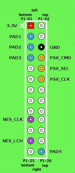
The pinout summary can be seen below. The power and ground pins are common for all pads, thus requiring splitters (i.e. a breadboard + pinheaders) when using multiple pads. Detailed information on connecting the pads can be found at the module's README (/usr/share/doc/gamecon_gpio_rpi/README.gz).
NOTE: Raspberry Pi Board revision 2 (all RPi variants manufactured after 09/2012) has different GPIO IDs for PAD1 & PAD2 pins, which must be taken into account when loading the driver.
The actual interconnect (NES/SNES/N64) can be made from female-to-female jumper wires and a single conductor wires with the other end folded in double (see here and here). For PSX pads, the jumper wires are enough by themselves. The only hard one is GC pad, which must be opened to make a good connection for the wires.
The easiest way to install the module is with the RetroPie-Setup script. Just remember to upgrade your firmware (sudo apt-get update; sudo apt-get upgrade) before installing the module, as it is built automatically using the configuration data from the latest RPi kernel. This also means that a firmware update afterwards can break the compatibility, but this is easily fixed by reconfiguration/update of the module (see FAQ).
Loading the module is done with modprobe, which is explained in detail in the README (/usr/share/doc/gamecon_gpio_rpi/README.gz).
In addition to install/update, RetroPie-Setup also contains an option to permanently enable configuration for 2 SNES pads connected to PAD2 & PAD3 pins (designed for the RetroPie GPIO Adapter).
Permanent configuration can also be done manually by adding a corresponding configuration line (eg: gamecon_gpio_rpi map=0,2) to /etc/modules
Related thread in Raspberry Pi forum.
- Add support for N64's rumble pak
-
Q: I get these errors when loading the module: "ERROR: could not insert 'gamecon_gpio_rpi': Exec format error", "gamecon_gpio_rpi: disagrees about version of symbol module_layout"
-
A: This means that the module has not been built against the current kernel version. This can happen if firmware is not up-to-date during installation, or by a firmware update afterwards. To fix this, remove and reinstall the drivers with the RetroPie-Setup script.
-
Q: NES pads only report A-button correctly, or do not react at all
-
A: NES controllers are designed to be used with 5V supply, and are not guaranteed to work directly with 3.3V supply. Based on various reports, pads tested seem to fall into 3 categories:
-
Fully 3.3V compliant. The pads falling into this category can be powered directly from 3.3V supply as described above, and do not need any extra hardware.
-
3.3V logic level compatible. These pads need to be powered from 5V supply (pin P1-02 on the RPi pin header) for correct operation, but RPi output pins (NES_CLK, NES_LTC) can be directly connected to corresponding pad input pins. A protection circuit is strongly recommended between pad output data pin and RPi input pin (PAD1-4), since output logic level is now 5V and input pins are not 5V-tolerant. The clamp circuit can be built from a 3.3V zener diode and ~200ohm resistor. Alternatively, a logic IC such as 74LVC245 can be used for level conversion.
-
Only 5V compliant. Otherwise same as previous, but NES_CLK and NES_LTC must be converted to 5V logic level to be recognizable by the pad. That can be done with 74HCT244 - see this post for more info.
-
Q: PSX pads do not operate reliably or at all
-
A: GPIO pins P1-07 and P1-26 do not have on-board pullup resistors which are required for reliable operation with PSX/PS2 pads. Connect an external pullup resistor (1.8k-4.7k) between the pin and 3.3V (P1-01) if you use it with PSX/PS2 pad.
-
Q: N64/GC pads do not operate reliably
-
A: These pads use an asynchronous communication prototol, and the bitbanging done by the driver assumes a fixed CPU frequency within certain limits. Power-saving features may break the operation, and should be disabled when using N64/GC pads. You can check whether frequency scaling is active by looking at /sys/devices/system/cpu/cpu0/cpufreq/scaling_* -nodes. It can be disabled by selecting "performance"-governor - see this page for more info.
- Optimized PSX driver code
- Added support for RPi2
- added support for rev.2 board gpio pins
- improved robustness with N64 / GC pad reads
- improved performance with PSX controllers
- restore psx_delay-option for setting psx access delay
- first DKMS-enabled version
- added support for GC and PSX controllers
- first release
db9_gpio_rpi is a driver (kernel module) for DB9 joysticks and gamepads connected to Raspberry Pi's GPIO. The driver is adapted from parport-targeted DB9 kernel module to GPIO, and has some additions and modifications. Connection of DB9 joysticks to RPi's GPIO requires no extra hardware in most cases, providing easy and cheap way for using retro joysticks with RetroPie.
The list of supported DB9 joysticks is below. Since the number of GPIO pins is limited, only 2 joysticks can be used simultaneously.
- Atari, Commodore, Amiga etc. db9 multisystem joysticks (1-3 buttons)
- Sega Mega Drive (Genesis) pads
- Sega Saturn controllers (Note: custom connector instead of db9)
- Amiga CD32 pads
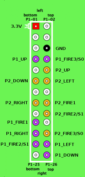
The available GPIOs are divided into 2 ports, PORT1 and PORT2. Both use 7 data pins, which are in identical locations on all RPi board variants. Additionally, the joysticks require either ground, or both ground and power pins depending on the type. These pins are common for both ports.
Pi's GPIO data pins operate at 3.3V and aren't 5V tolerant (see this), so 3.3V '''must''' be used for joysticks requiring power even though they'd be designed for 5V. However, some TTL-based joysticks may not function correctly using 3.3V supply. If they need to be powered from 5V, level shifters must be added between output pins of joystick and GPIO input pins. For example, 74LVC245 is an IC which can be used for this downconversion.
Below is an illustration which shows the pins used by the driver, with the mappings listed in a table next to it. Pin numbers are identical for all board revisions: the image represents the complete gpio block for A/B boards, and the top portion of the gpio block of A+/B+/Model B boards.

|
|
| DB9 pin | Atari basic joystick | C64 joystick | MD/Genesis pad | Saturn controller (non-db9) | CD32 pad |
|---|---|---|---|---|---|
| 1 | UP | UP | UP | - | UP |
| 2 | DOWN | DOWN | DOWN | DOWN | DOWN |
| 3 | LEFT | LEFT | LEFT | UP | LEFT |
| 4 | RIGHT | RIGHT | RIGHT | SELECT0 | RIGHT |
| 5 | - | - | 3.3V | SELECT1 | SELECT0 |
| 6 | FIRE1 | FIRE1 | FIRE1 | 3.3V | SELECT1 |
| 7 | - | 3.3V | SELECT0 | RIGHT | 3.3V |
| 8 | GND | GND | GND | LEFT | GND |
| 9 | - | - | FIRE2 | GND | FIRE1 |
More information on the connections is provided in the driver README (/usr/share/doc/db9_gpio_rpi/README.gz).
The module is loaded and configured with modprobe. This is explained shortly in the parent page and in detail in the driver README. The joystick IDs for modprobe are listed below:
| ID | Description |
|---|---|
| 0 | (No joystick) |
| 1 | Multisystem 1-button joystick |
| 2 | Multisystem 2-button joystick |
| 3 | Multisystem 3-button joystick |
| 4 | MD/Genesis pad (3+1 buttons) |
| 5 | MD/Genesis pad (5+1 buttons) |
| 6 | MD/Genesis pad (6+2 buttons) |
| 7 | Sega Saturn controller |
| 8 | Amiga CD32 gamepad |
Related thread in Raspberry Pi forum.
- Q: I get these errors when loading the module: "ERROR: could not insert 'db9_gpio_rpi': Exec format error", "db9_gpio_rpi: disagrees about version of symbol module_layout"
- A: This means that the module has not been built against the current kernel version. This can happen if the fw is not up-to-date during installation, or by a fw update afterwards. To fix this, run "Install/update multi-console gamepad drivers for GPIO"-option in RetroPie setup.
- Added support for RPi2
- Fixed issues with 3rd-party MD pads
- first release
