Building - keirf/pcb-projects GitHub Wiki
To build a switcher for A500 or A600 you will need the following parts:
- STM32 "Blue Pill" board
- USB-TTL serial adapter
- 12-pin 2.54mm-pitch right-angled single-row PCB header
- PC motherboard speaker/buzzer
- Hookup wire (kynar or similar)
- Suitable capacity EPROM: 27C160 (up to 4 images), 27C322 (up to 8 images)
- Firmware programming file (Download [Google Drive])
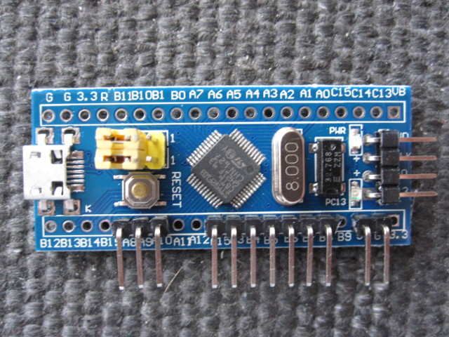
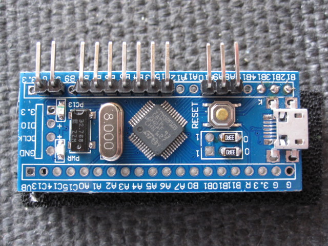
First cut the PCB header into 2-pin, 3-pin and 7-pin sections. Solder these along one side of the bare STM32 board as show below. Make sure the headers are installed straight and even.
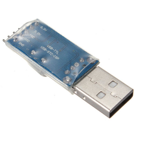
Next we program the STM32. You will need a USB-TTL adapter such as shown below, available for around £1 on Ebay. My own experience is with the PL2303HX-based adapters, which are automatically detected and initialised in Linux. In Windows the correct Prolific driver is installed, but since the cheap adapters are using cloned chips, the driver may fail to initialise the device. In this case the driver must be replaced by an older version and auto-update disabled for the driver, as described here.
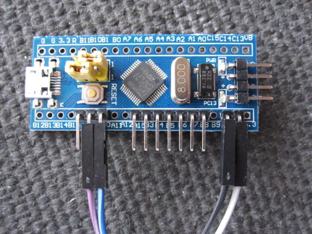
Now adjust the yellow boot jumpers on the STM32 board and attach the Dupont jumper cables supplied with the USB-TTL adapter as shown. In this example the cables connect to the following USB-TTL pins: White to GND, Black to 5V, Purple to RXD, Blue to TXD.
Download the firmware zip file from here [Google Drive]. On Linux the firmware HEX image can now be programmed with the stm32flash command-line utility:
 # unzip kswitch_v2.zip
 # sudo stm32flash -vw kswitch_v2/kswitch.hex /dev/ttyUSB0
Once the device is programmed you can remove the boot and debug headers. The boot-select pins should be forced to 00 by bridging the appropriate through holes with wire or low-value chip resistors as shown.
If fitting to an A500 with its top shield intact you may also wish to remove the USB socket. The mounting tabs can be snipped with small side cutters and the socket then gently pulled off.
Finally, you must configure the firmware via the serial line. Connect to the console via a serial terminal at 115200 baud, 8 data bits, no parity, 1 stop bit, and reset the STM32 board. On Windows you could use PuTTY, among many other options. On Linux, you can use Python's miniterm utility:
 # sudo miniterm.py /dev/ttyUSB0 115200
 > 1
 > <your number of images>
 > 12
Or, while connected to the console, press the reset button to view the current configuration and the full range of menu options.
This step requires a blank 27C160 or 27C322. Also typically you will use a TL866 programmer and the 27C160/322 adapter which I build and sell. You require 512kB ROM images which are 'byte-swapped' (bytes in each 16-bit word are swapped). If this is done correctly then, when loaded into the MiniPro programming software, the Kickstart copyright message will appear in the buffer window ungarbled. If it's garbled, you haven't swapped! If you are using a 256kB image (eg Kickstart 1.3) then double it up.
In Linux or MacOS terminals, the double-up and byte swap could be done as follows:
 # dd if=kick13.rom of=kick13_swapped.rom conv=swab
 # cat kick13_swapped.rom >kick13_swapped_doubled.rom
 # cat kick13_swapped.rom >>kick13_swapped_doubled.rom
On Windows you will have to find your own way!
Plug my adapter into the TL866 and set the jumpers to
A20/A19/A18=0/0/0. Select device 27C4096 and deselect Check ID.Insert the EPROM into the adapter. Load your default ROM image and
program the EPROM.
Now load your second ROM image, select A20/A19/A18=0/0/1, and program
the EPROM.
Continue this process for your remaining ROM images, setting the
jumpers in this sequence: 0/1/0, 0/1/1, 1/0/0, 1/0/1, 1/1/0,
1/1/1,
The 27C160/27C322 must be physically modified to support the Kickstart switcher. The below steps are for a 27C322 device. They also apply to 27C160 but ignore references to pin 32 and leave it unmodified!
-
Cut pins 1 (A18), 42 (A19), and 32 (A20, 27C322 only) short, but with enough left to solder onto.
-
Flux pins 1, 22, 31, 32 (27C322 only), and 42.
-
Apply solder to all fluxed pins and then attach a short piece of hookup wire ('Kynar' wire, or a strand from an ATA 80 ribbon cable is appropriate here) to each one.
-
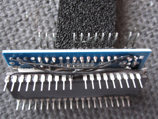
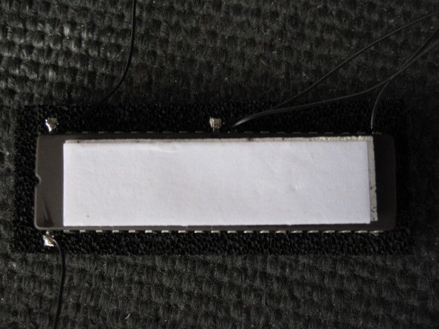
Attach the switcher to the top of the EPROM with hot glue or double-sided foam tape with the angled headers on the right-hand side. Pre-programmed EPROMs are supplied with tape already installed.
-
Connect pin 22 (VCC) to 5V on the switcher.
-
Connect pin 31 (VSS) to G (GND) on the switcher.
-
Connect pin 1 (A18) to B12 on the switcher.
-
Connect pin 42 (A19) to B13 on the switcher.
-
27C322 only: Connect pin 32 (A20) to B14 on the switcher.