20220930 Nixdorf 8850 - jsheradin/kb_adventures GitHub Wiki
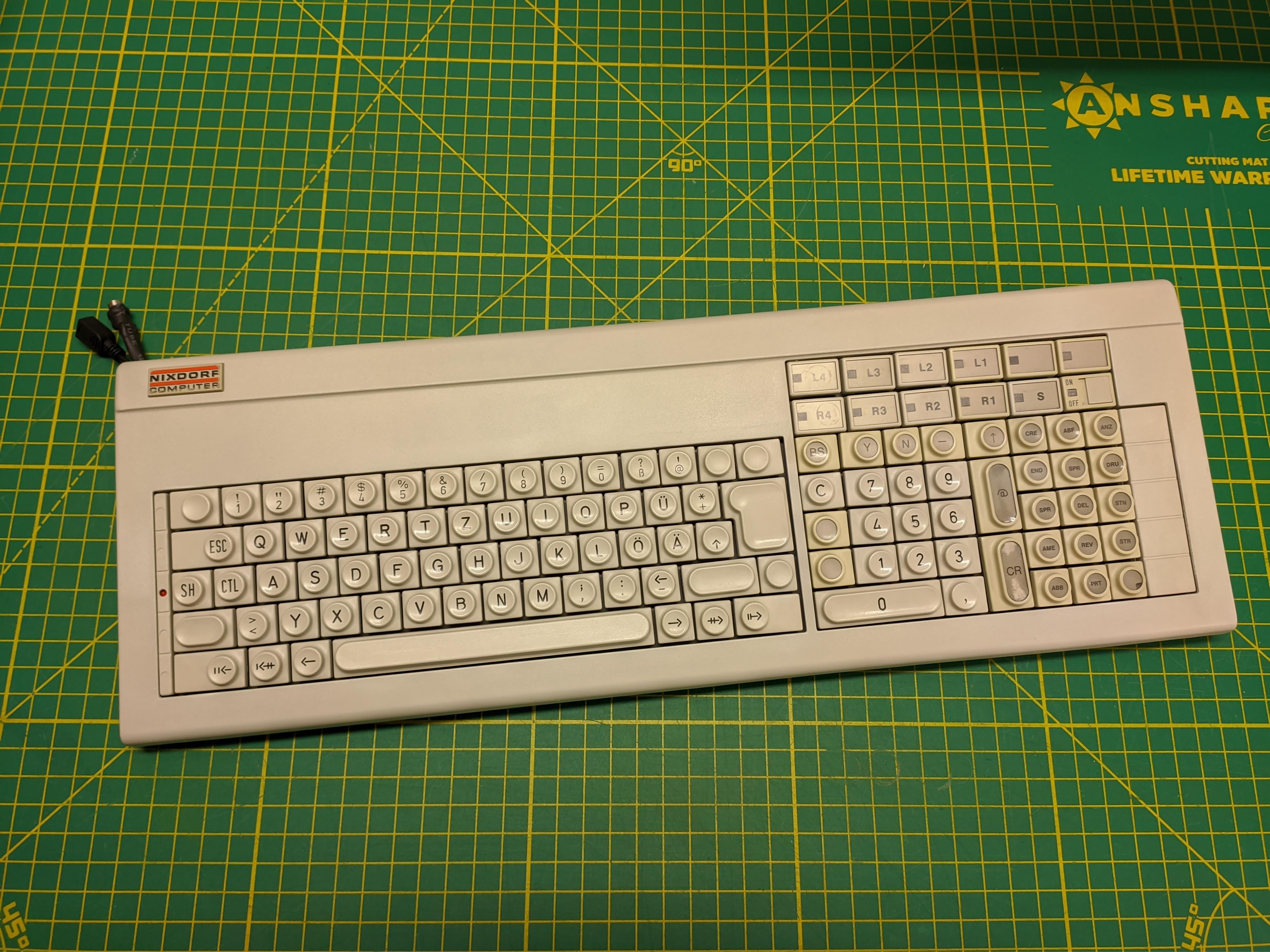
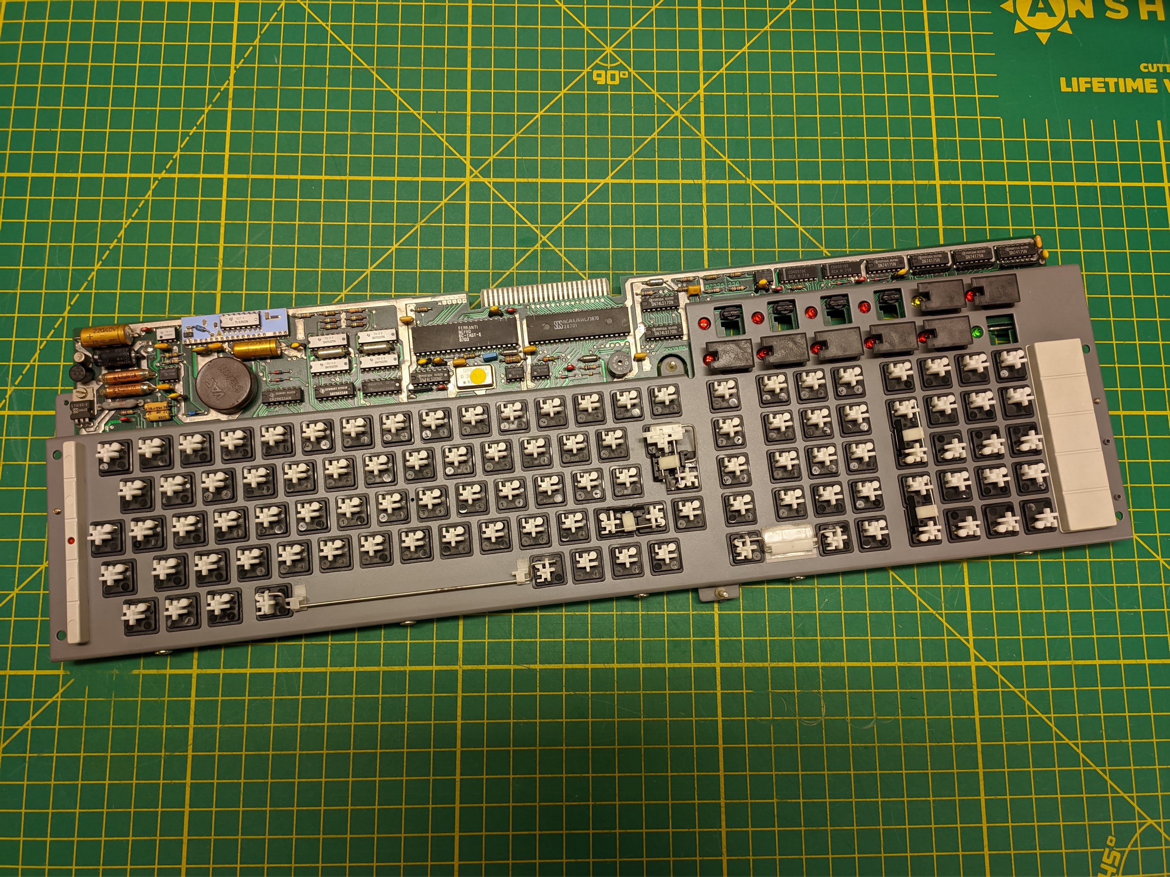
I believe this keyboard was designed by people who have never seen a keyboard before. It's about as far from traditional as possible in all aspects. Even the case omits the traditional screws or clips in favor of a cammed latch mechanism. Albeit weirdly shaped, it features doubleshot keycaps with the windowed keys having noticeably different yellowing. I'm not sure if they're a different plastic or if it's just a different formulation of UV stabilizer.

Switches
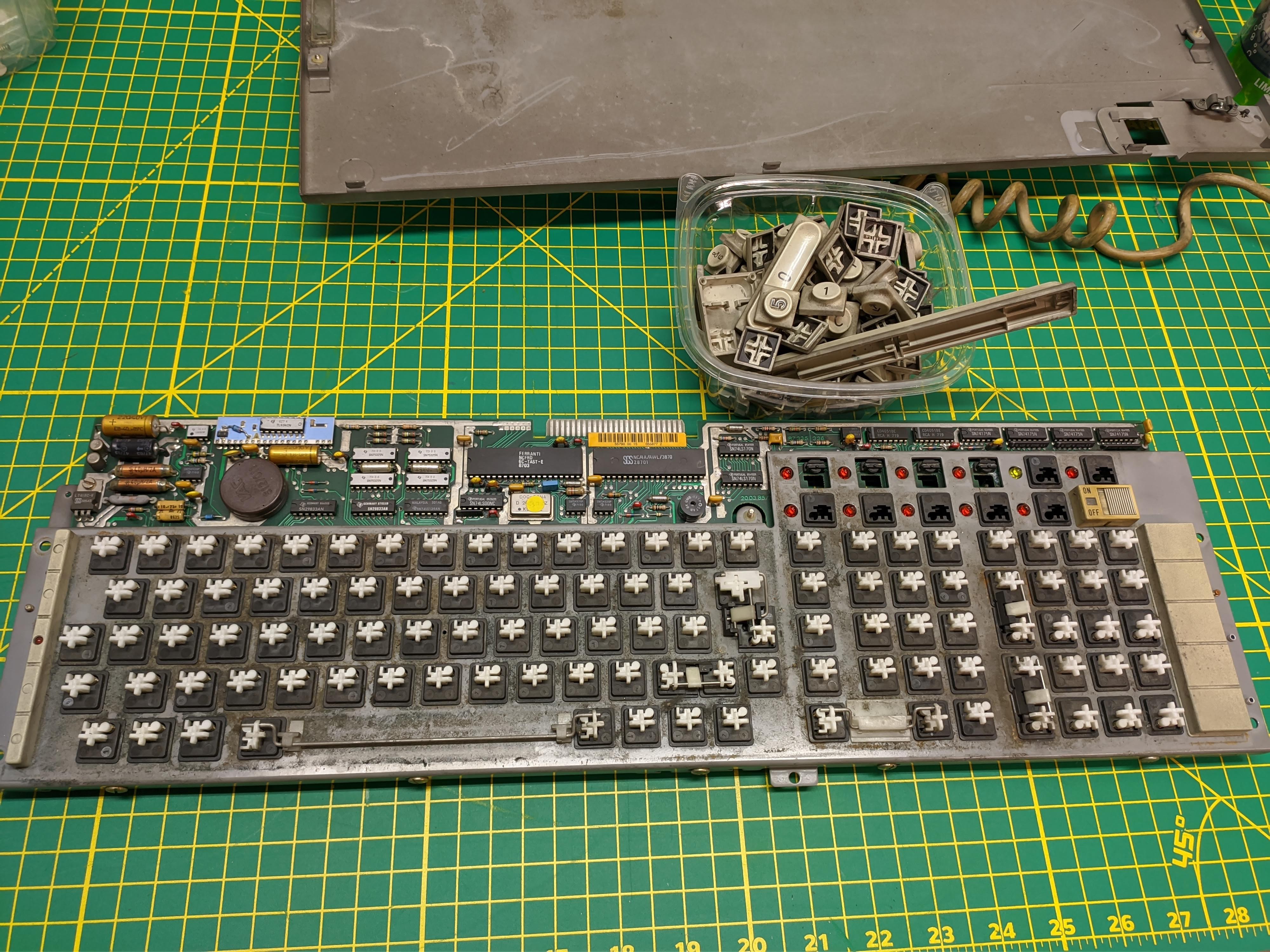
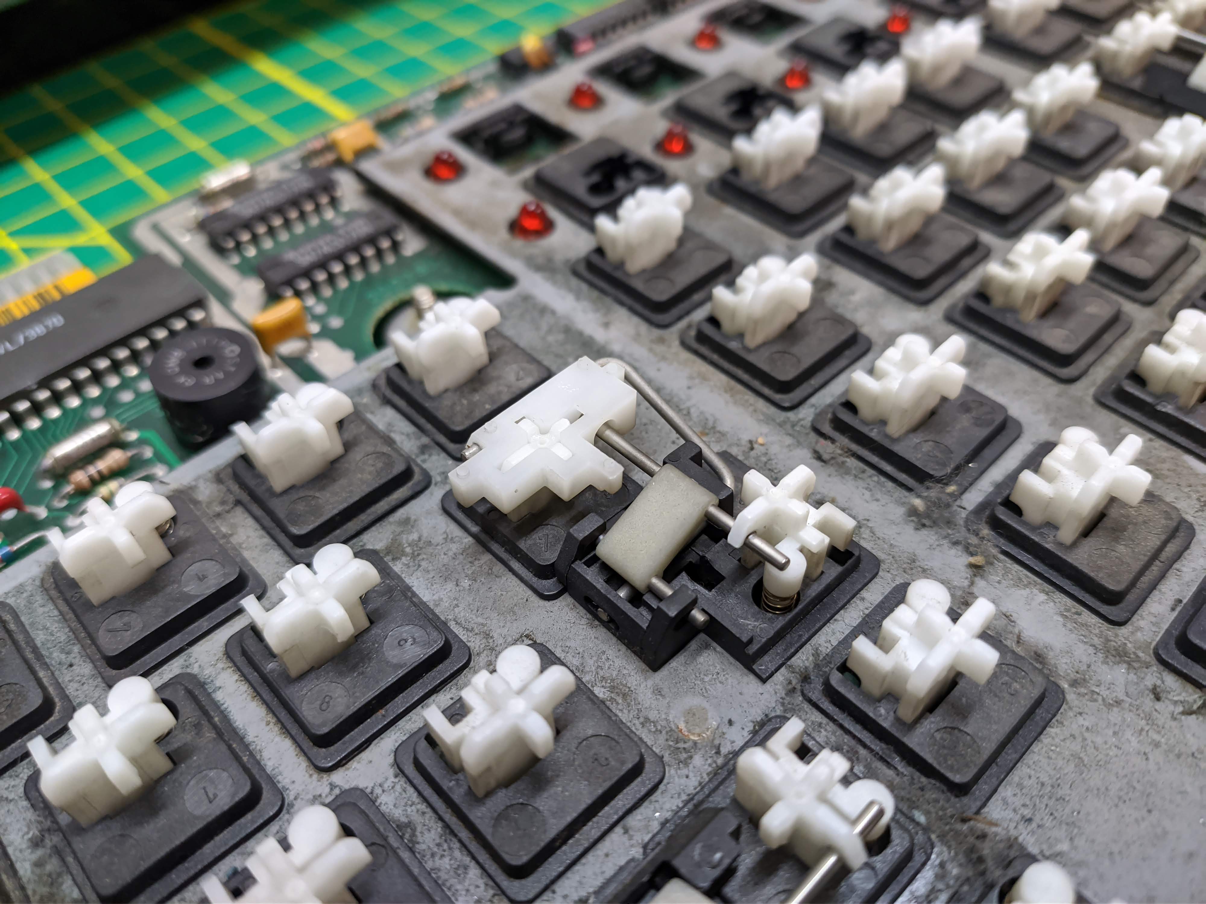
The switches are unique to Nixdorf and were only used in a handful of boards. They are a very low profile design with a couple unique approaches to match that goal. The stem actually protrudes through the PCB when pressed, thus they can sit lower to the PCB. The spring is offset to a corner of the switch allowing it to be parallel to the stem instead of under. The switches are damped in both up and down directions by a small rubber bumper which also acts as a pin to hold the stem in.

The actual technology running the board is the comparatively rare inductive sense matrix. Each switch has two coils around a ferrite core with the stem containing a magnet. The position of the magnet changes the magnetic saturation of the core. In the unpressed state, the core is fully saturated and there is no signal passed from one coil to the other. If the magnet is moved away there is more room in the core for flux generated by the primary coil thus more current is induced in the secondary coil. By recording the induced current in the secondary, you can determine the position of the switch. This is effectively the same approach used by ITW's magnetic valve switches.

Cleaning
The board was either in a hookah parlor or a burning building. There was a ton of sticky soot coating every surface. All the plastic parts were washed in soapy water with the help of an ultrasonic cleaner. The case and yellowed caps were tossed in the sous-vide-retrobrighter. The case turned out great but the yellowed windowed keys really didn't want to give up the color. I decided not to push it too hard with peroxide concentration or temperature for fear of clouding the windows.
The PCB was scrubbed with isopropyl alcohol. The switch plate had some rust spots so it was sanded back to metal and hit with some color matching enamel paint. Springs were washed in isopropyl alcohol and coated with a plastic safe rust preventative coating. Switches and stabilizers were lubed with a light coat of Tribosys 3204 and the board fell back together.


Conversion
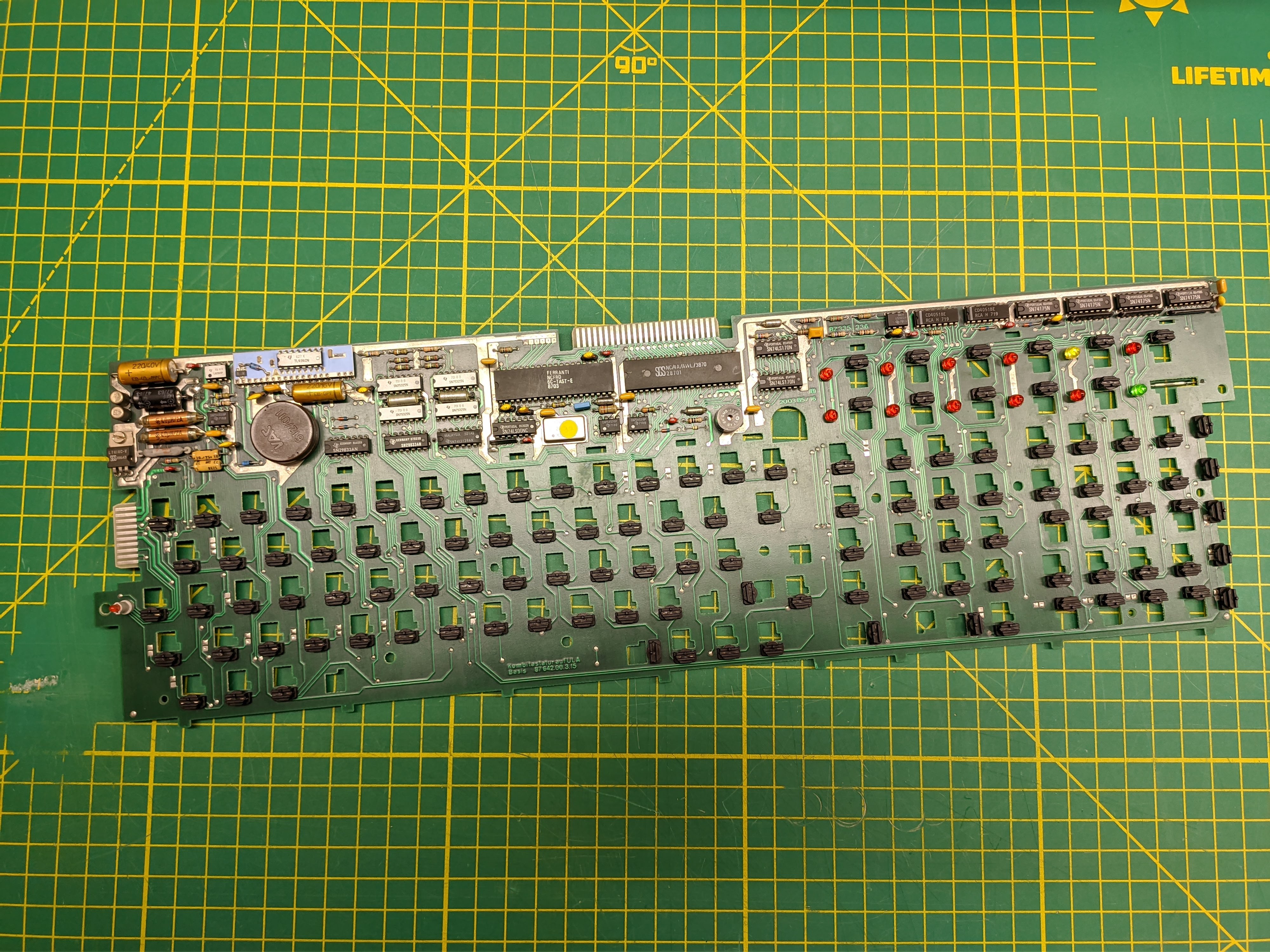
This switch design requires some pretty high currents to drive the matrix. The board regulates the input DC power down to 18V and 5V. It's not possible to run the board solely on 5V since part of the matrix driver circuit actually uses 18V. The input voltage needs to be a bit above 18 due to the drop of the regulator. 24V is in the regulator's happy spot and is reasonably common so there were plenty of adapters to choose from. The input power to the board is around 20W so you'll need at least a 1A supply. This is evidently well before the days of power consumption concerns. A couple chips in the board exceed 40C when fully warmed up.
Giving the board power showed signs of life but nothing on the output. I could probably gut the board and get it working with something like DMA's Commonsense but I would like to keep the original controller if possible. Documentation on the 8850 is non-existent. There's a handy site about the 8870 with a good bit of archived info. Unfortunately, among all of the docs, there's only a single paragraph dedicated to the keyboard. It hints at an insanely fast serial protocol that requires handshaking, error correction, etc in order to function. I gave it a solid effort but completely ran up dry getting the board to talk over the proper connector.
Eventually I moved my focus onto an internal card-edge connector. I'm not sure if it was ever utilized for another machine or if it was just for diagnostics and factory testing but it was unused in this board. Regardless, there was actual activity on the lines instead of the dead silence of the cable connector. With the help of a logic analyzer I found a series of frequency halving clocks very similar to that of the IBM 4979's keyboard. The Nixdorf differed in that the clocks were constantly iterating regardless of the position of any keys. I kept probing around and found two additional lines that cracked the protocol wide open, clock and state.
On the rising edge of the clock signal you simultaneously read in the status of the state line (1 bit) and the current address represented by the halving clocks (8 bits). These 9 bits correspond to the live press state of every key on the matrix. The board is feeding key information at around 16kHz, pretty speedy but nothing that a modern micro-controller can't handle. Unfortunately the bus I'm tapping into is one way so I don't have any control over the LEDs on the board.
After reading a good chunk of the 32u4 datasheet I set up some ports for direct IO access and configured an interrupt and handler for the rising edge clock signal. A quick Arduino script helped by spitting out the address every time a key was pressed. The board is full NKRO with every key unique except for left/right shift. Once I had the address corresponding to every key on the board I tossed the interrupt routine into QMK, set up a buffer and matrix handler function, and finally made a basic key map. After fixing some dumb syntax issues it compiled to a hex file that worked on the first attempt! The only hardware needed is a DC power brick and a Teensy 2.0.

