20220922 IBM 4979 - jsheradin/kb_adventures GitHub Wiki
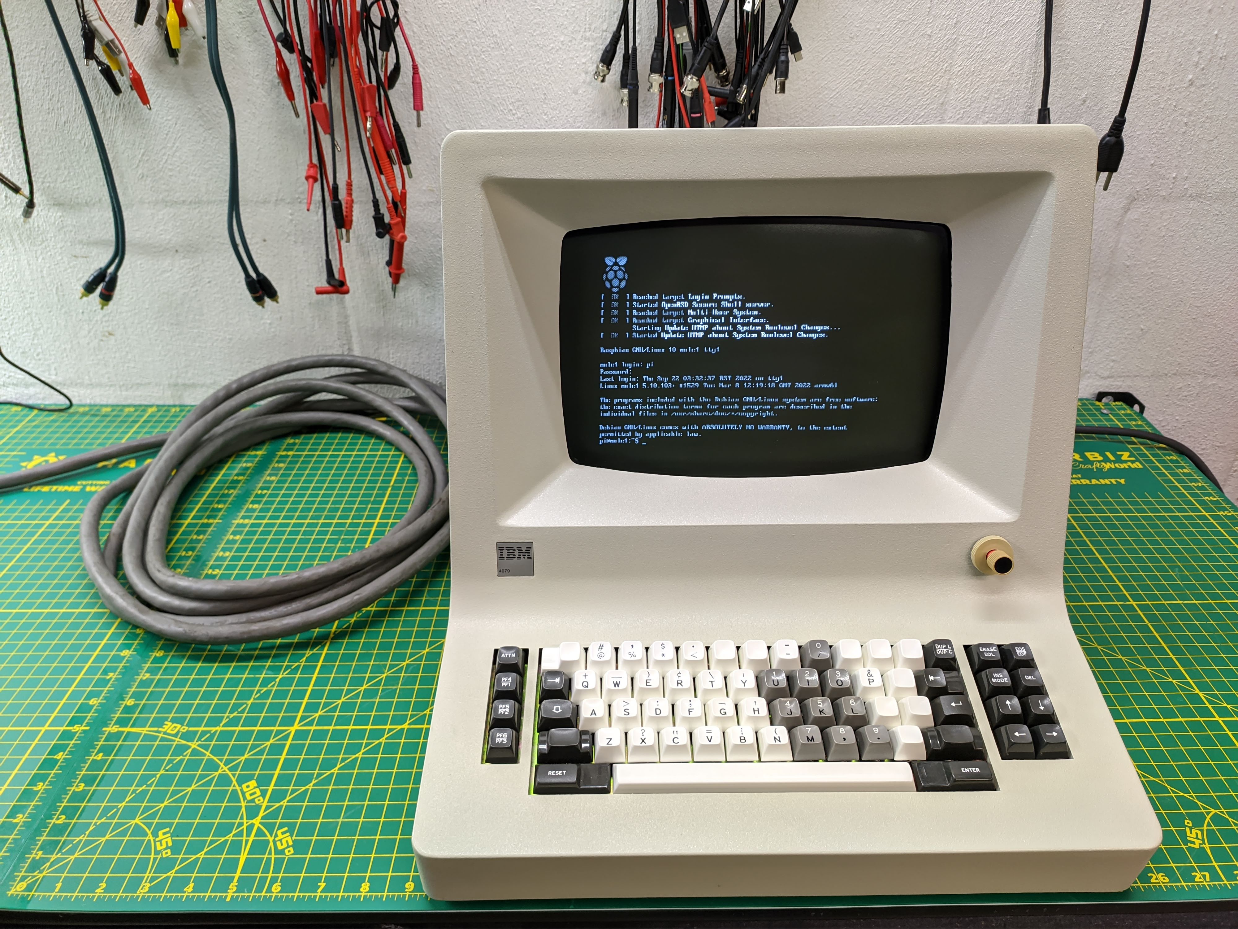
This particular terminal was manufactured in 1979 and has been out of service for quite a few years. It's part of IBM's Series/1 minicomputer ecosystem which launched in 1976. The Series/1 supported a number of operator interfaces using both remote and local protocols. The 4979 is considered a locally-connected terminal since it plugs directly into a matching add-in card in the Series/1. There's some documentation archived on Bitsavers but it's only for the terminal/card pair as a whole. I only have the terminal half and there's no documentation that I can find which describes the functions of each or the data link between them.
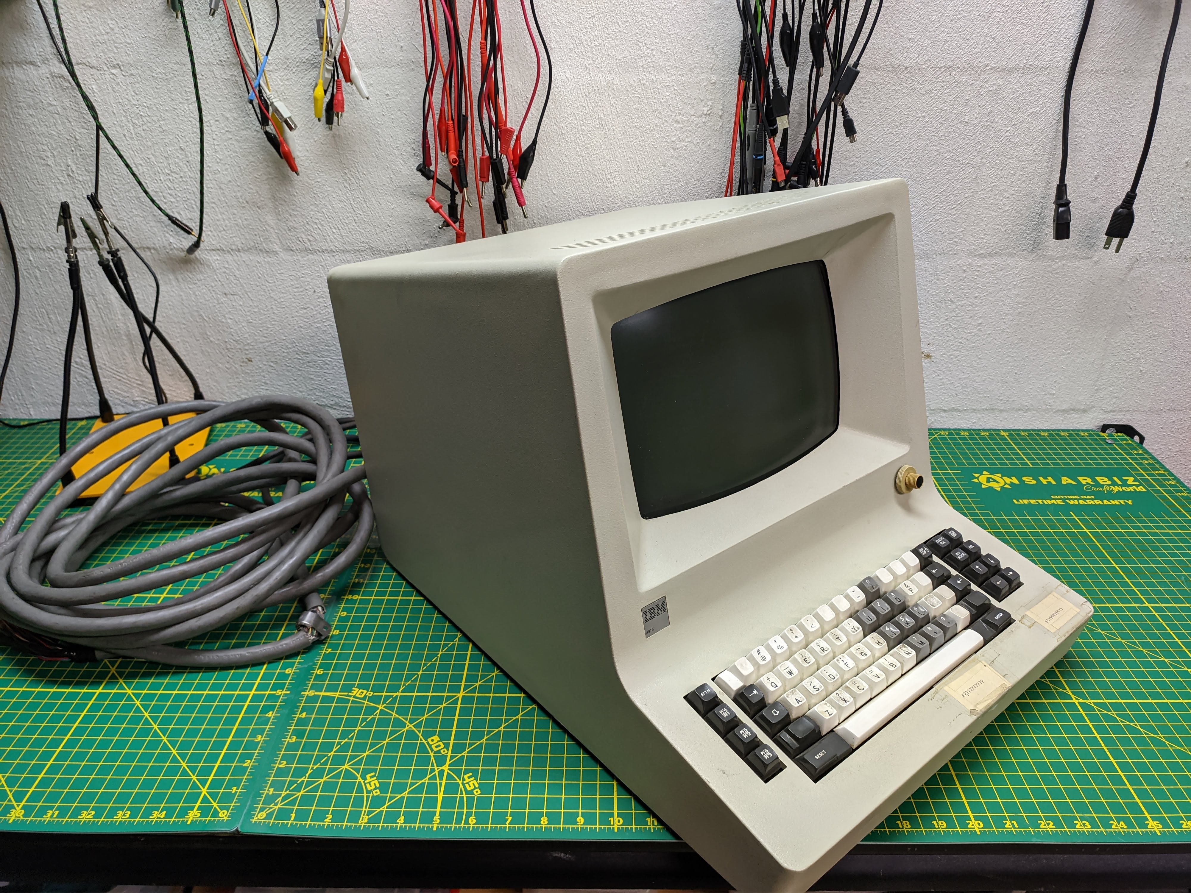
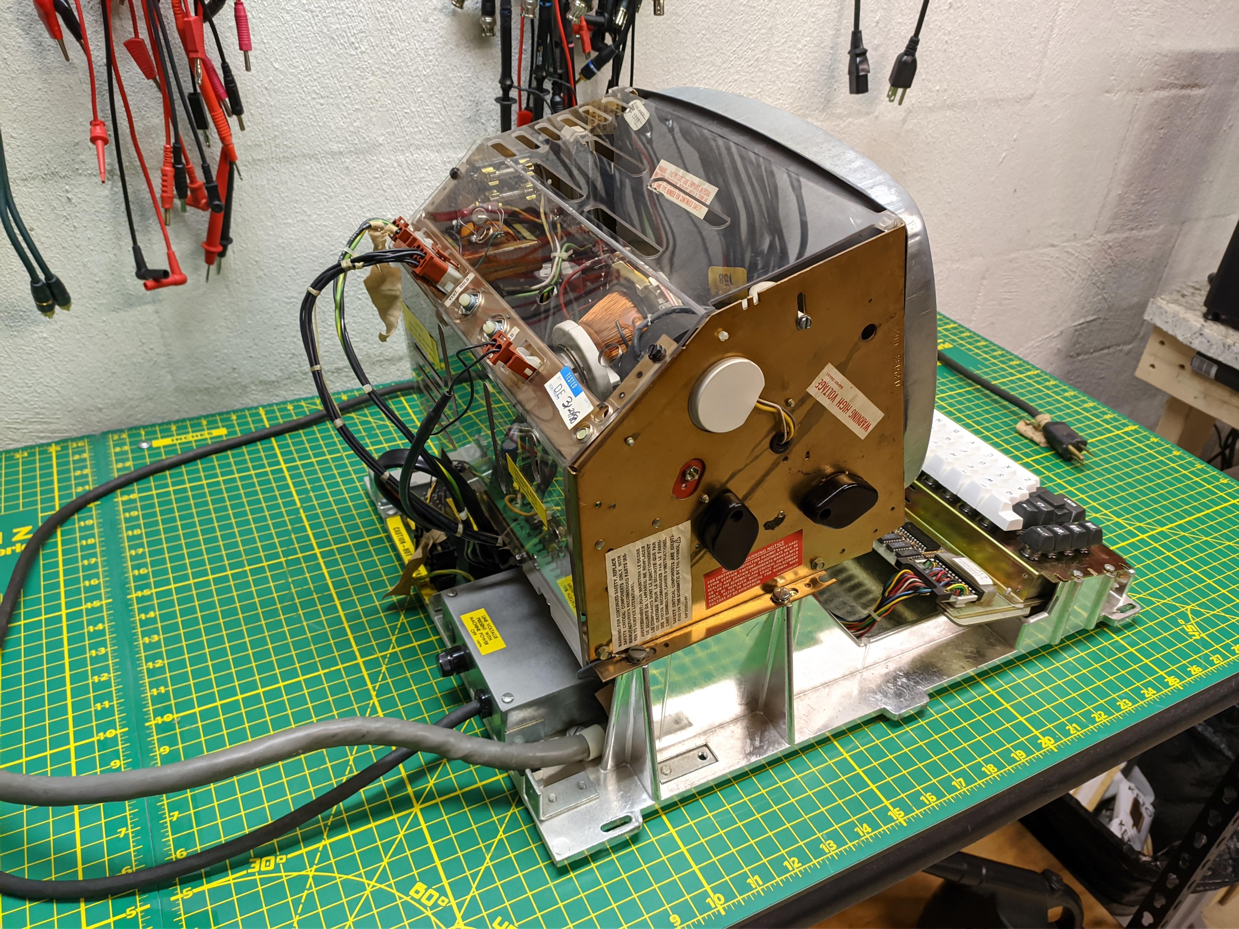
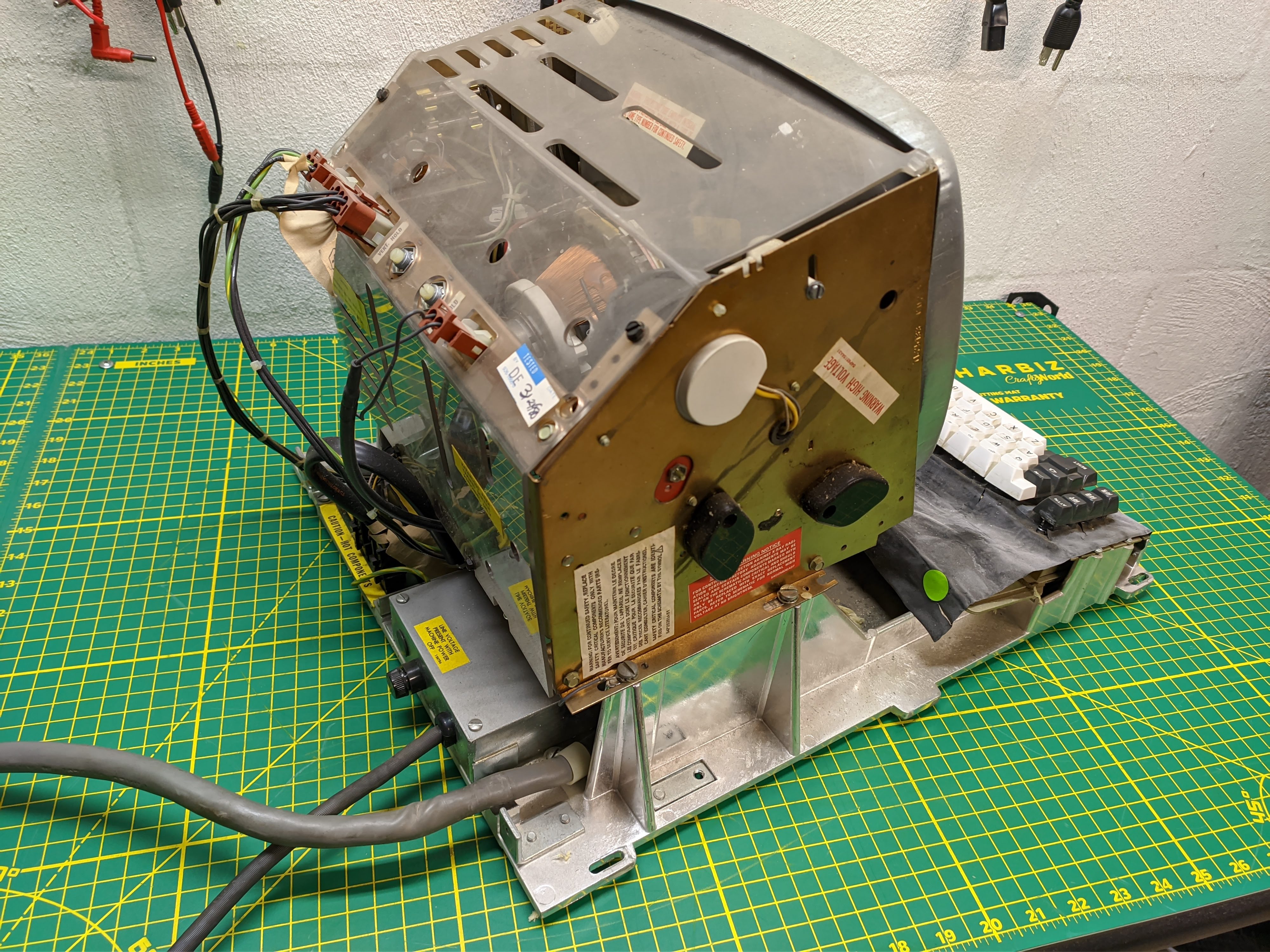
Overall the terminal is in very good condition. There's the expected deterioration of beamspring materials and a solid layer of dust and grime but barely any corrosion and no significant damage or missing parts. Visual inspection and LCR probing showed promising results. An insulation health check shows that there's no obvious ground faults so I pulled the trigger and powered it up. No smoke was released and it indeed appears to be in marginally functioning order. The 5V PSU was spot on at 5.015V and the CRT gave off the high pitched 15.75kHz whine.

Keyboard
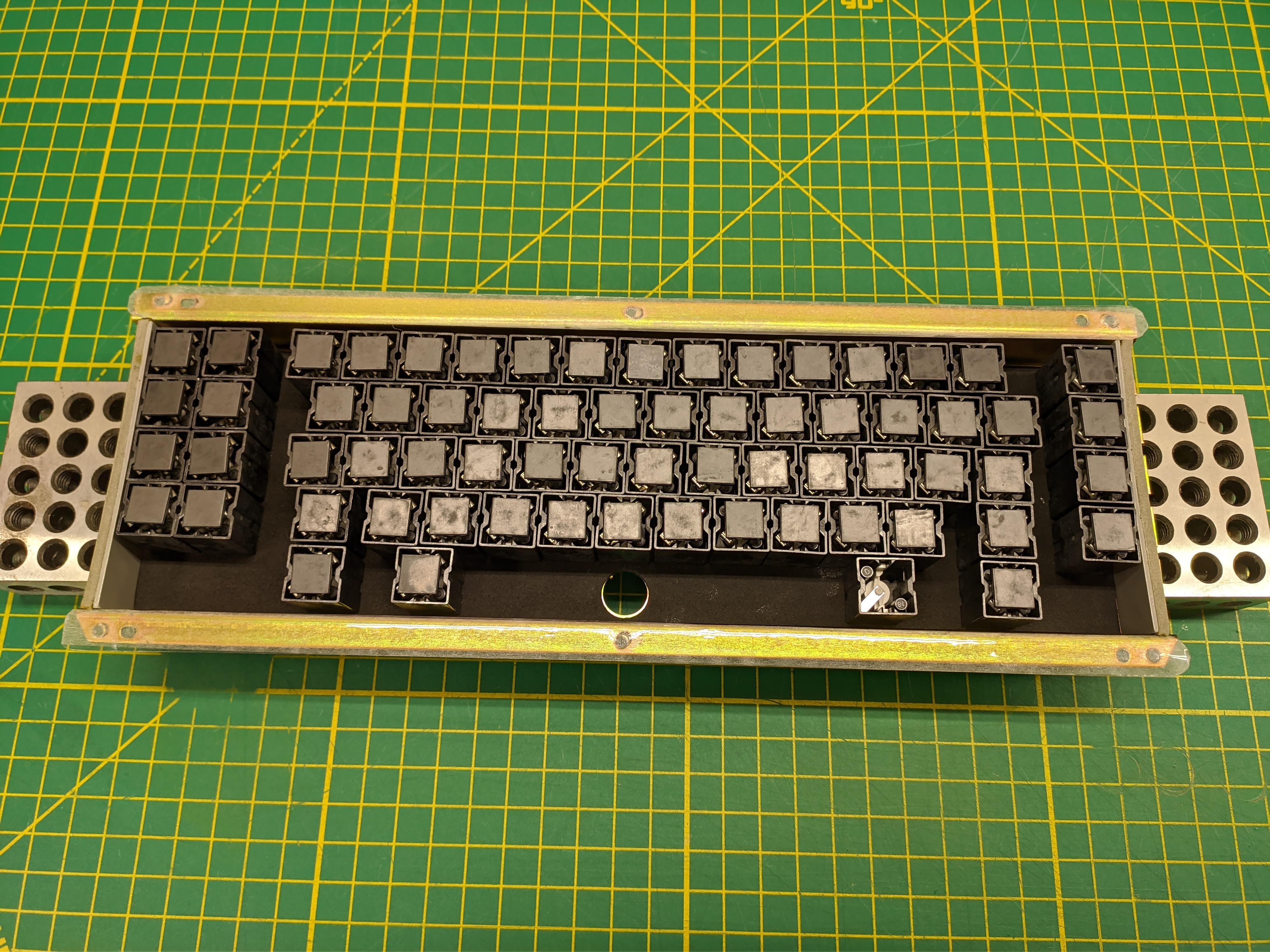
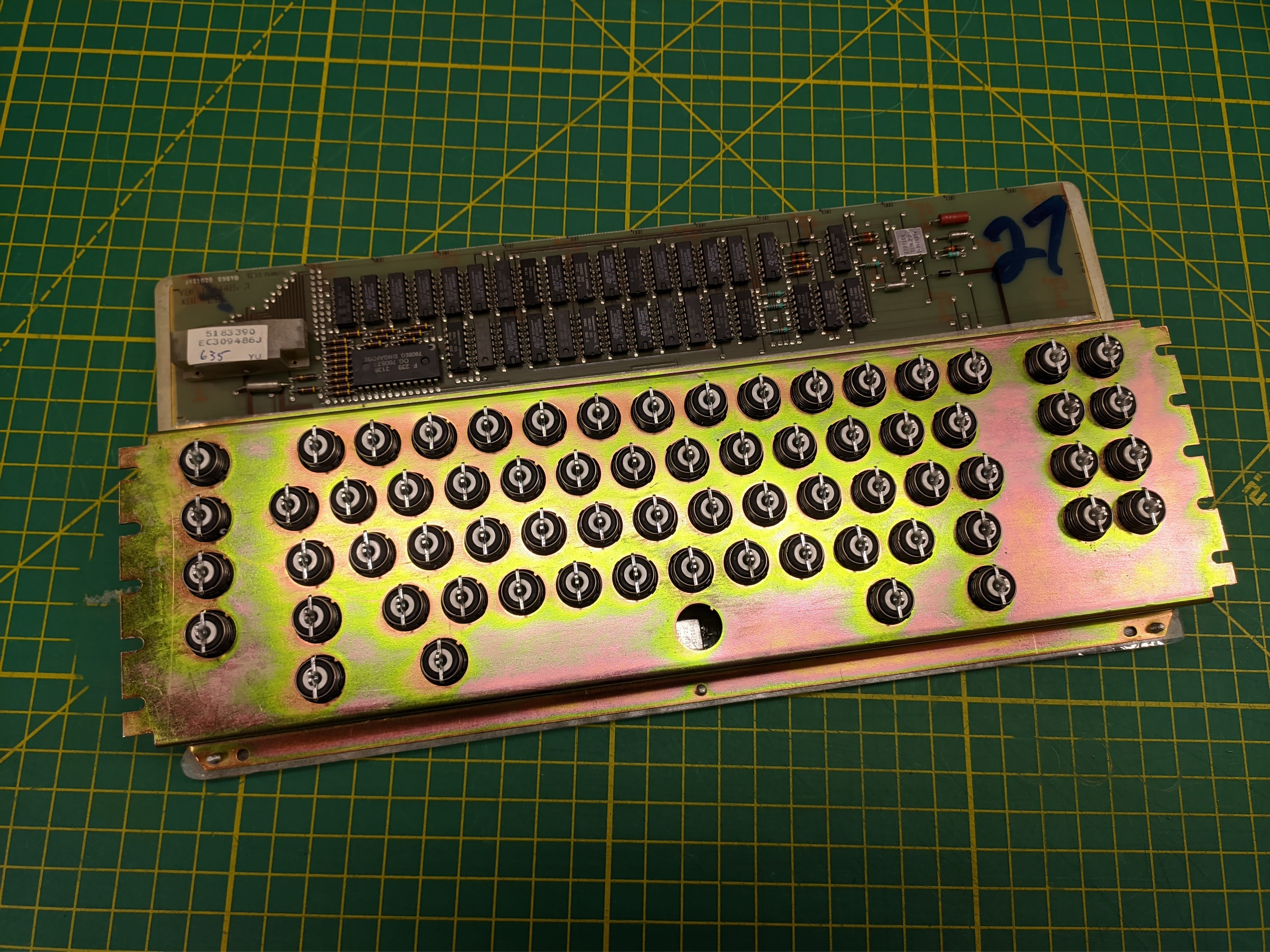
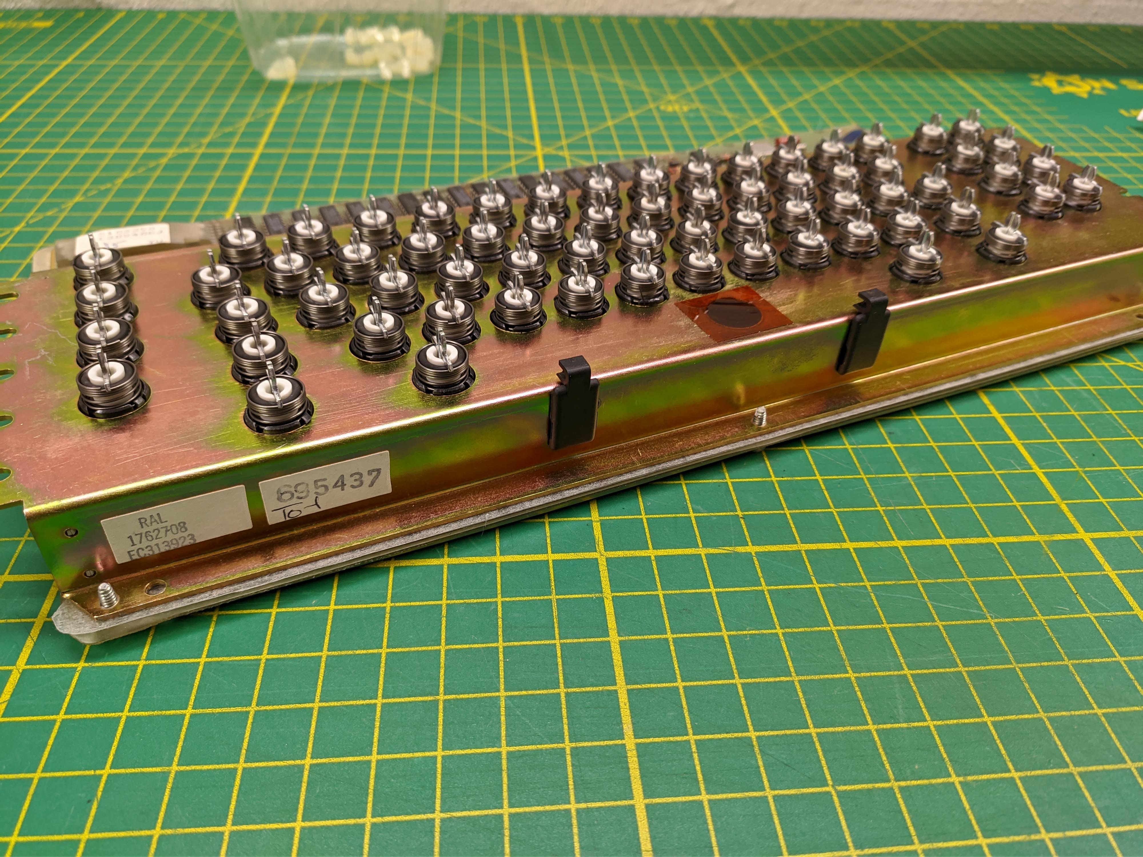
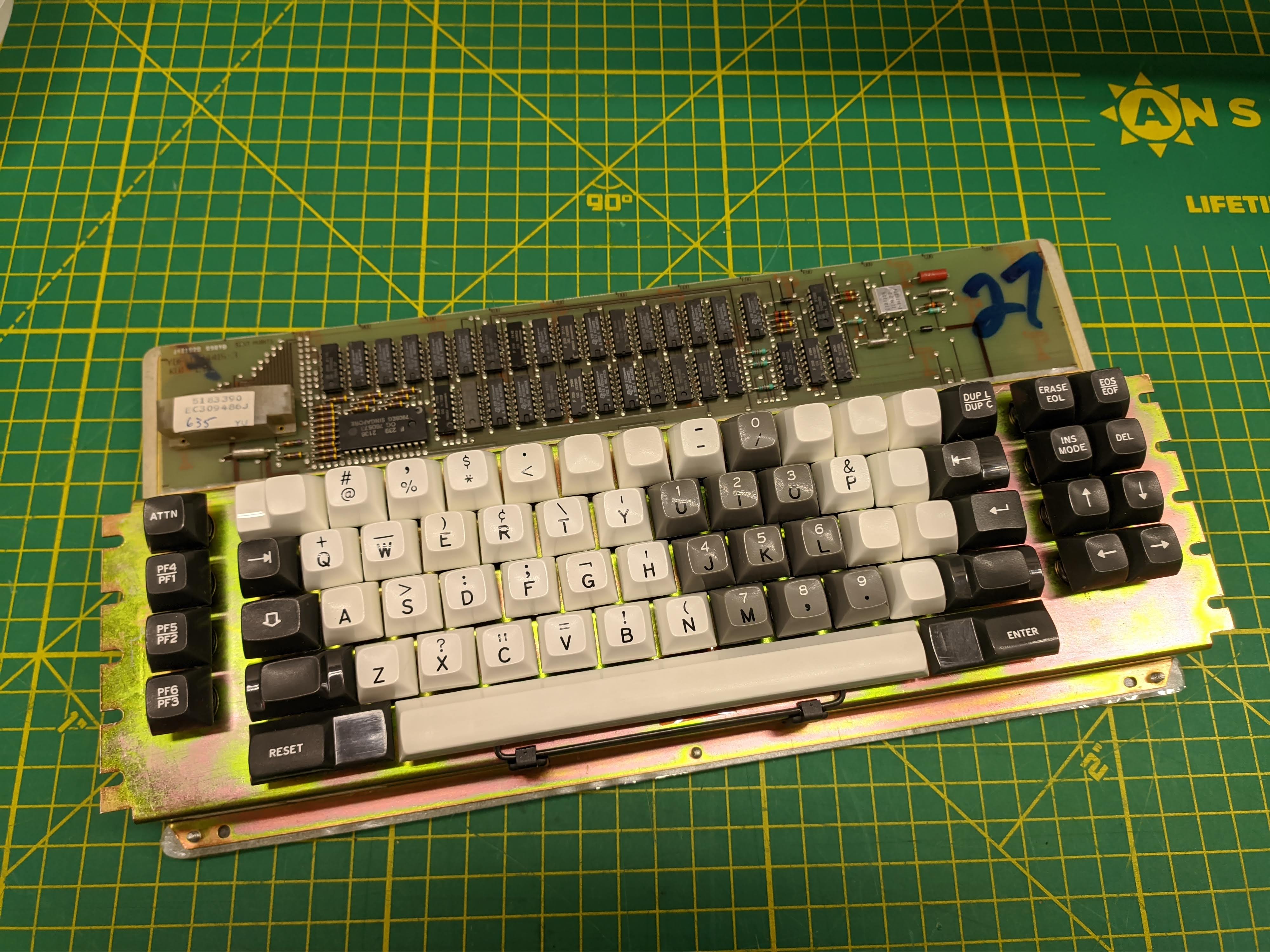
The keyboard is a 66-key beamspring with all the capacitve sensing goodness that entails. The caps are brilliantly white with not even a hint of yellow. They don't fluoresce under UV light so I suspect they're either not standard ABS or IBM used a particularly good UV stabilizer when mixing them up. Alphas and modifiers are doubleshot while the numberpad is tripleshot.
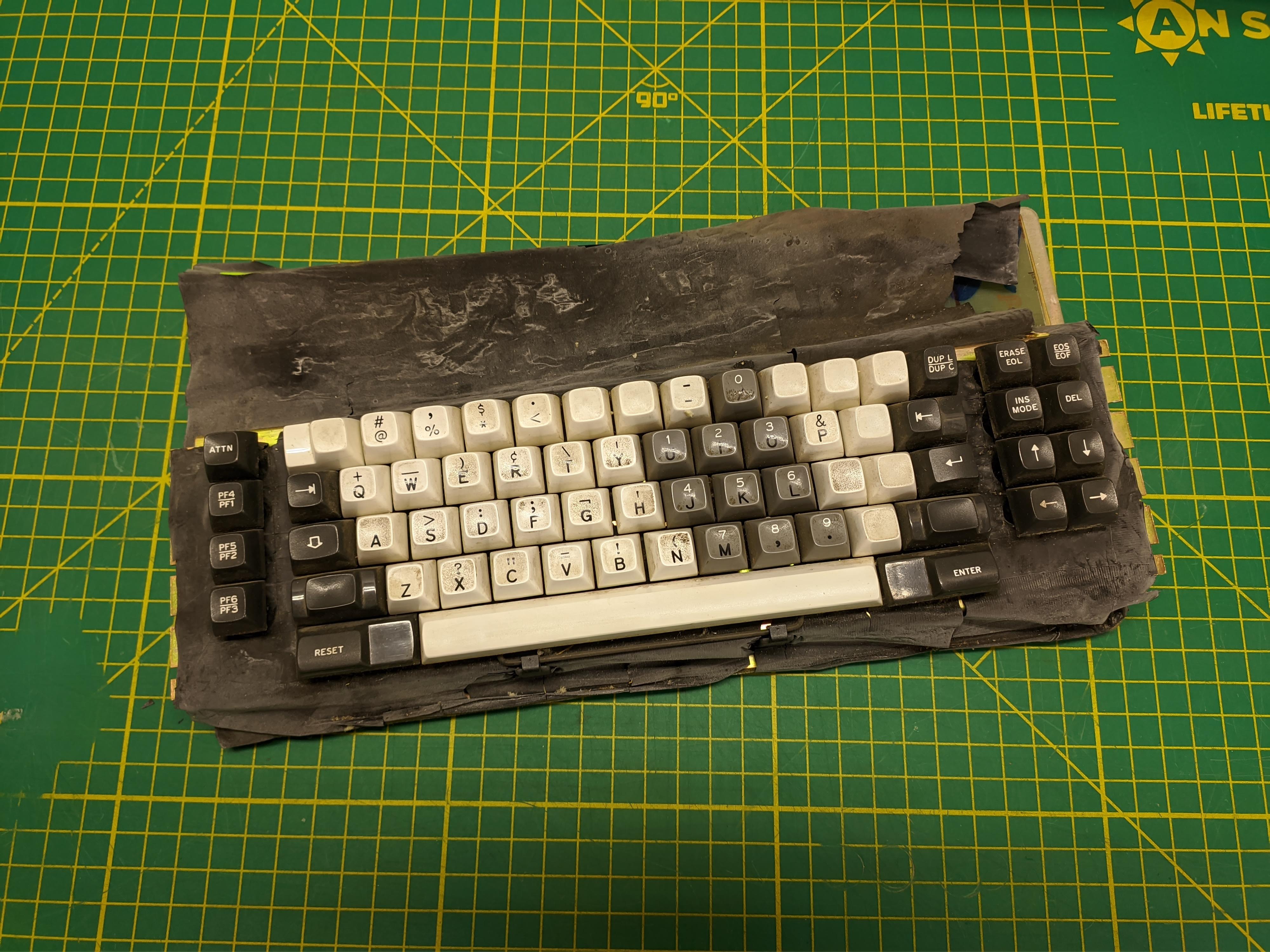
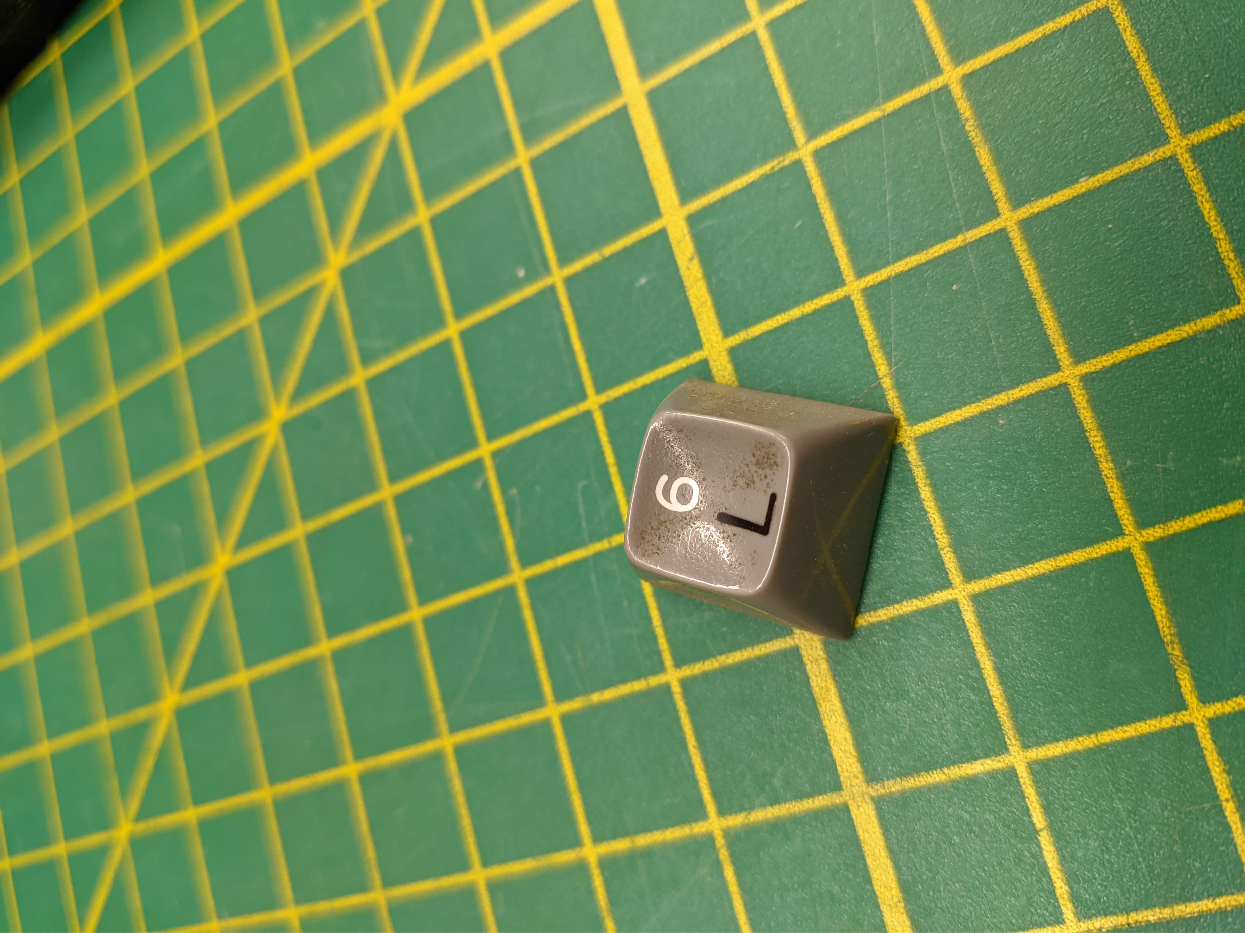
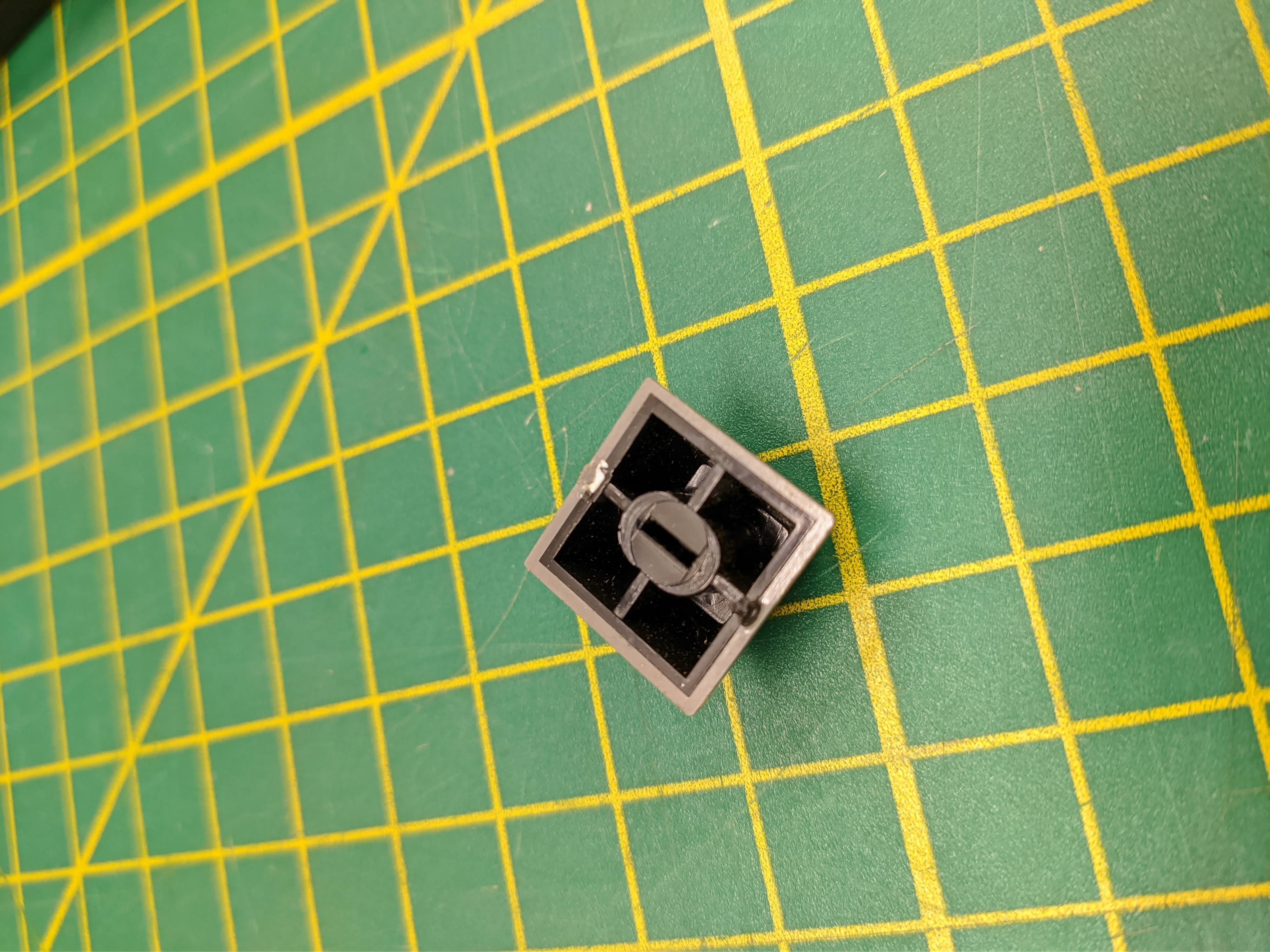

The manual shows quite a few international layouts but being a US model all it had was a bunch of blanks (the blanks were still doubleshot interestingly). The blank keys all had blockers around the stem to prevent them from being pressed. Removing the blockers revealed that they're indeed fully funtional switches. I opted to leave the blockers off since I had a feeling the board was the same underneath for all layouts. If this terminal is ever used with a real Series/1 someday I assume it will throw an error if you press them.
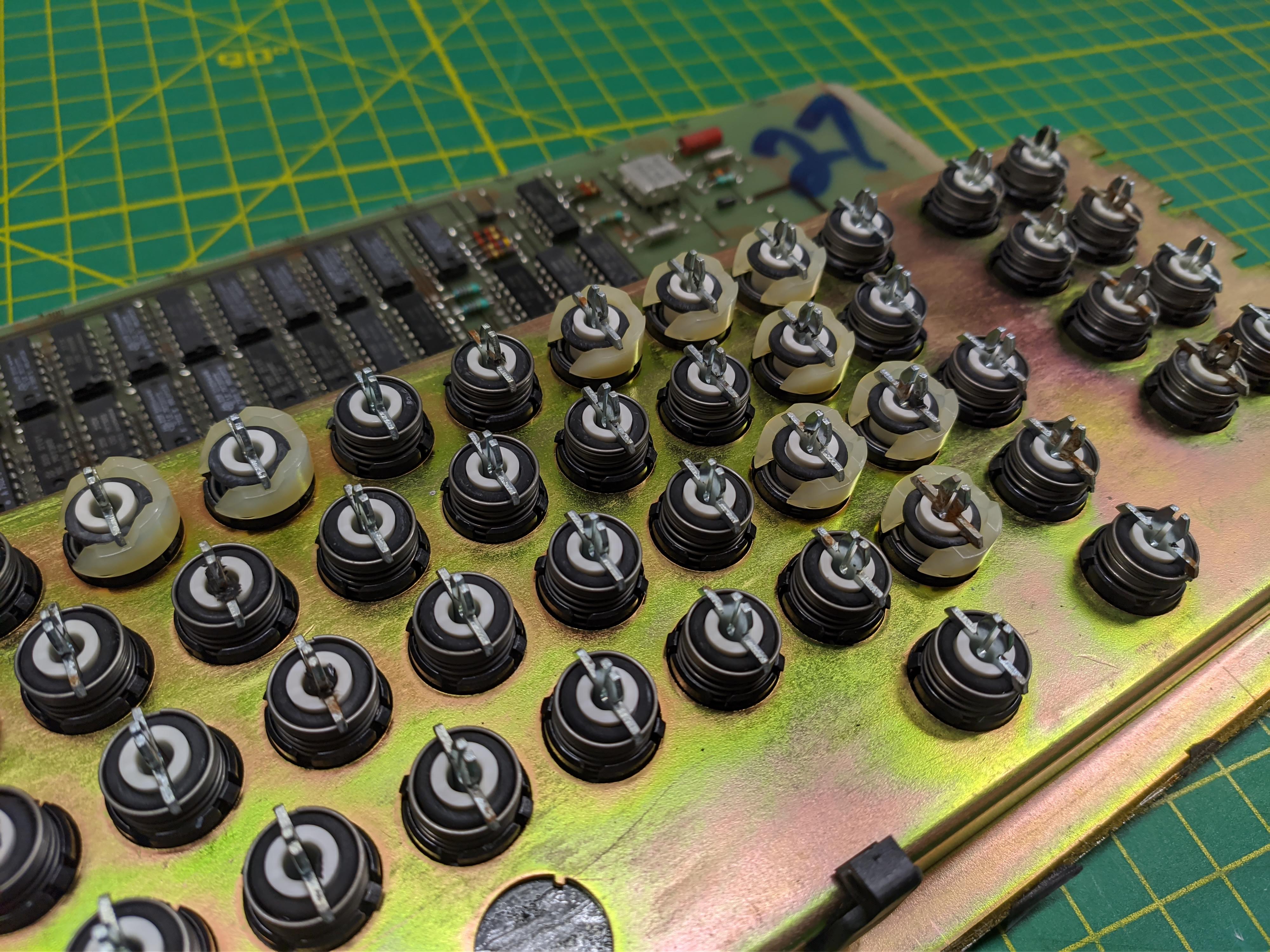
Being a beamspring it suffers from the usual degradation. Interestingly, the outsides of the switch housings were covered in a crystalized residue or possibly shedding glass fiber fill. I'm not sure if that's related to something off-gassing from the foam as it decayed or if it was just a weirdly mixed batch of plastic. The insides of the housings were fine and it cleaned up easily.
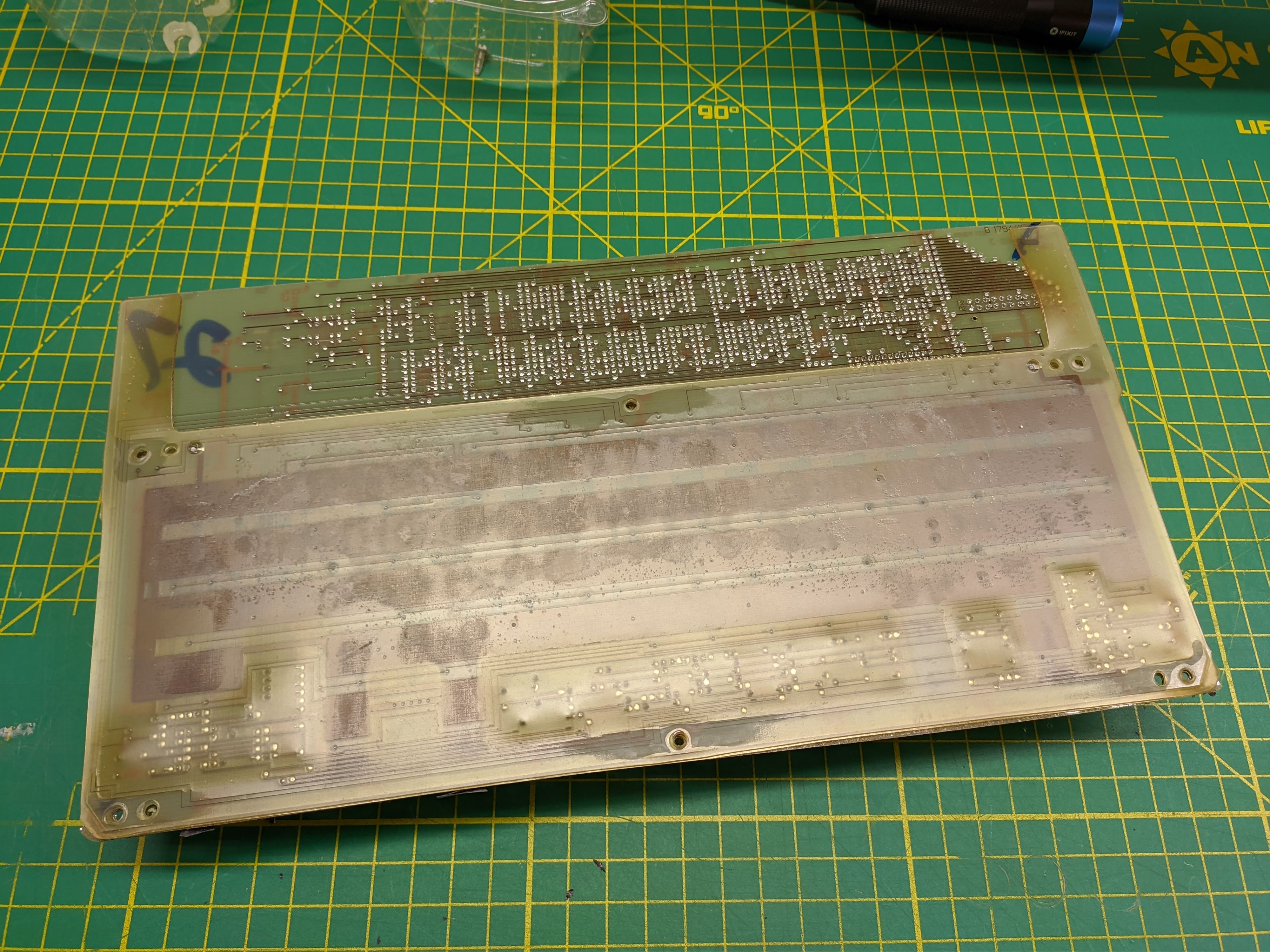
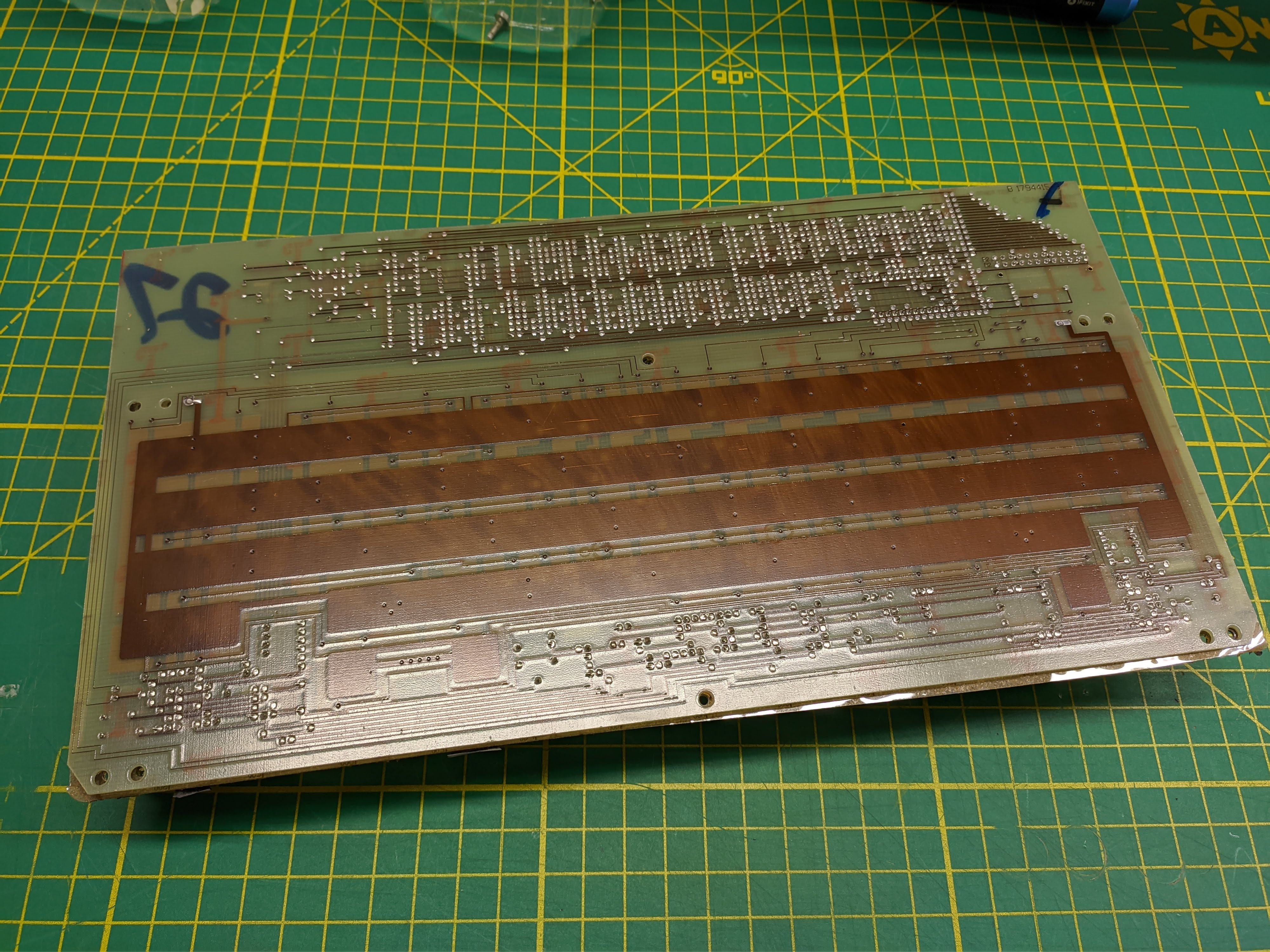
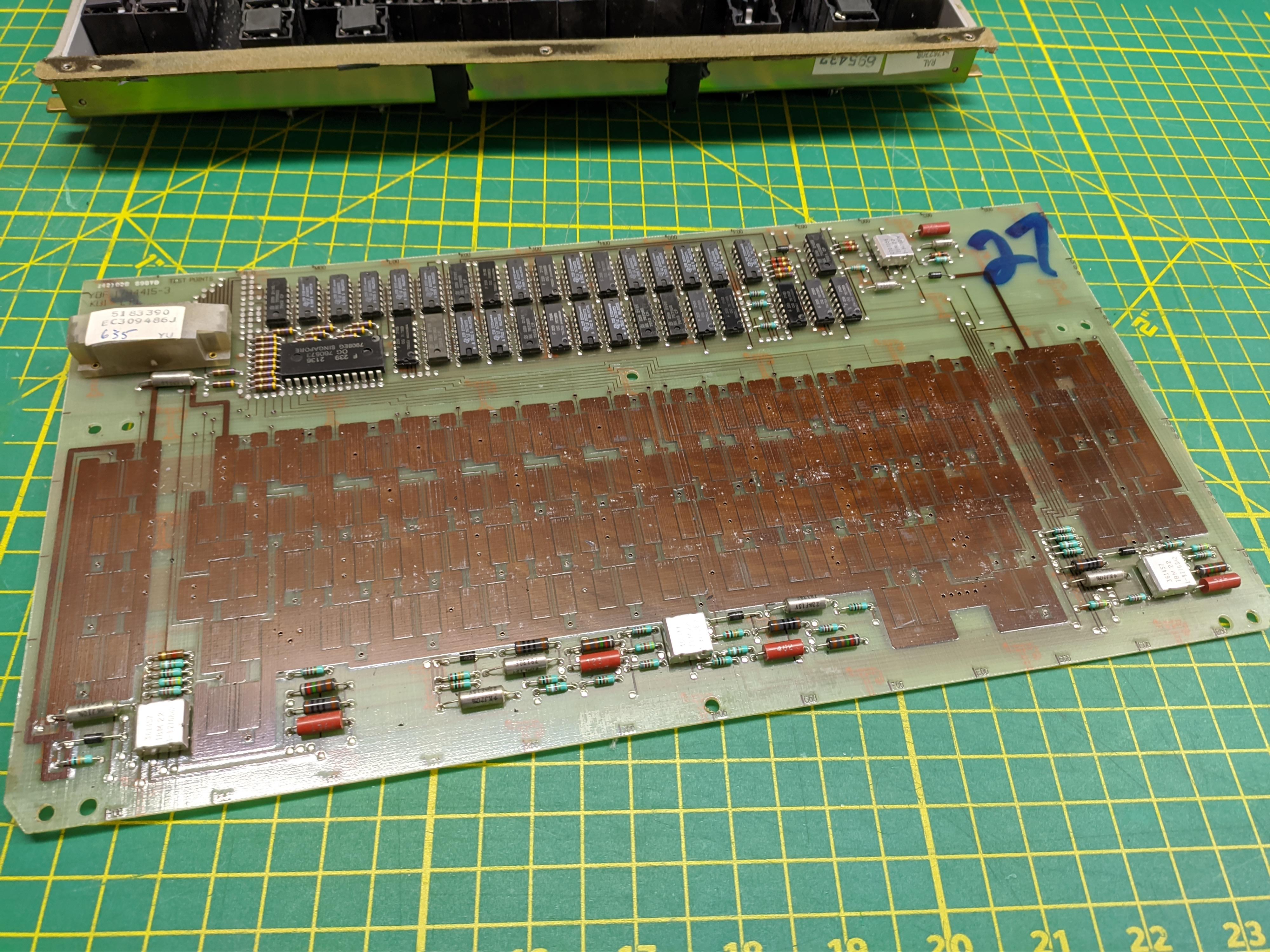
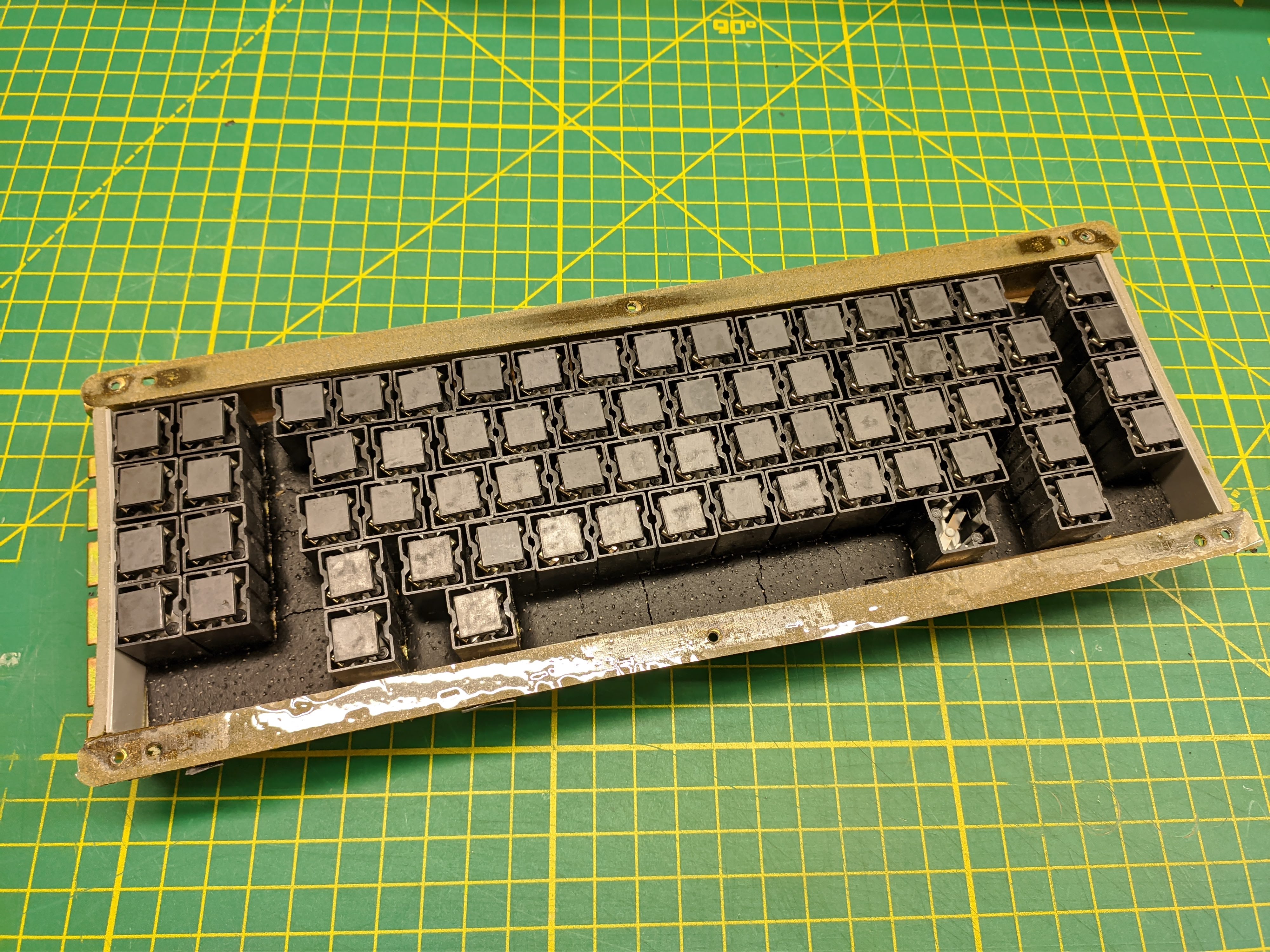
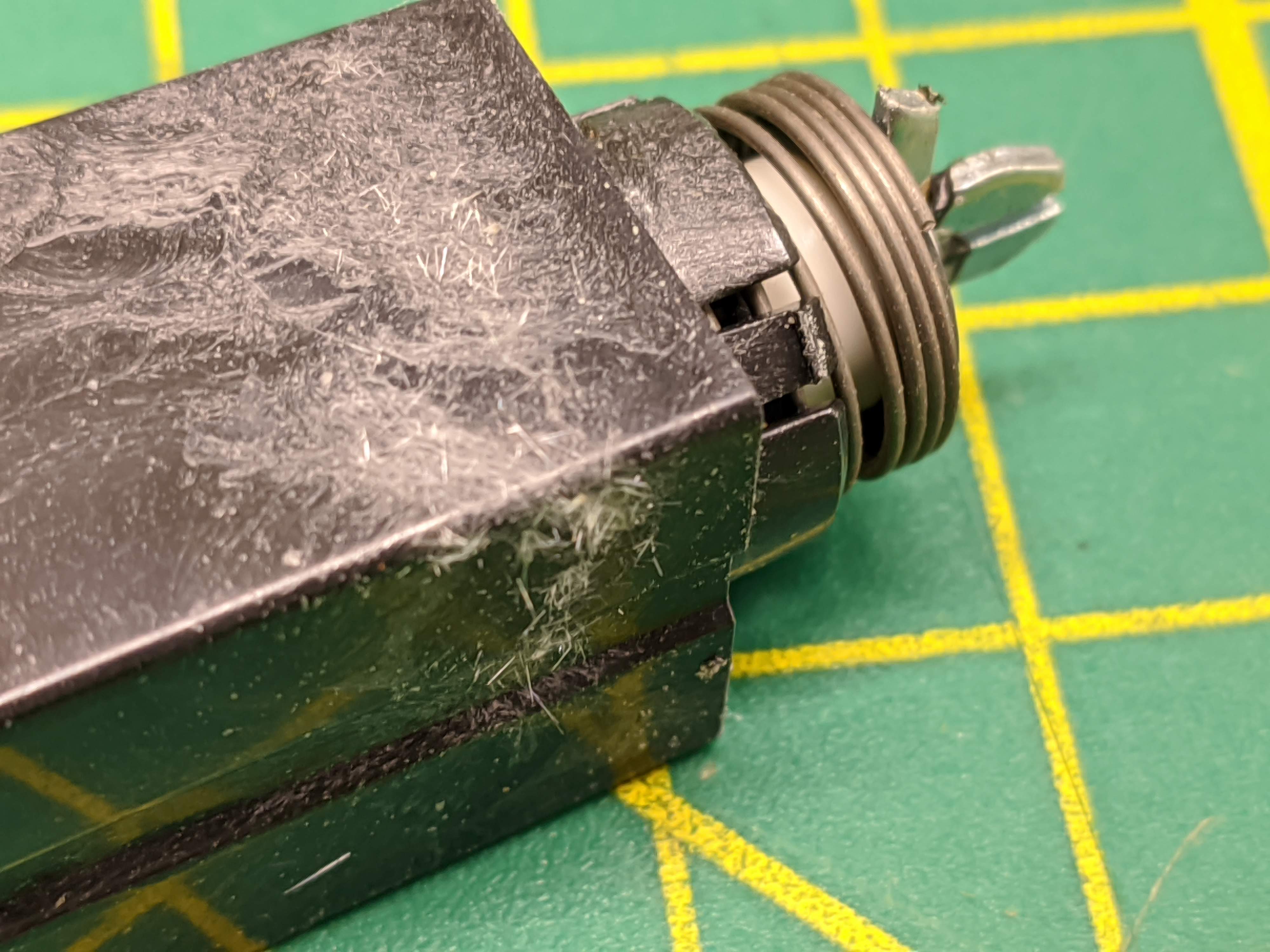
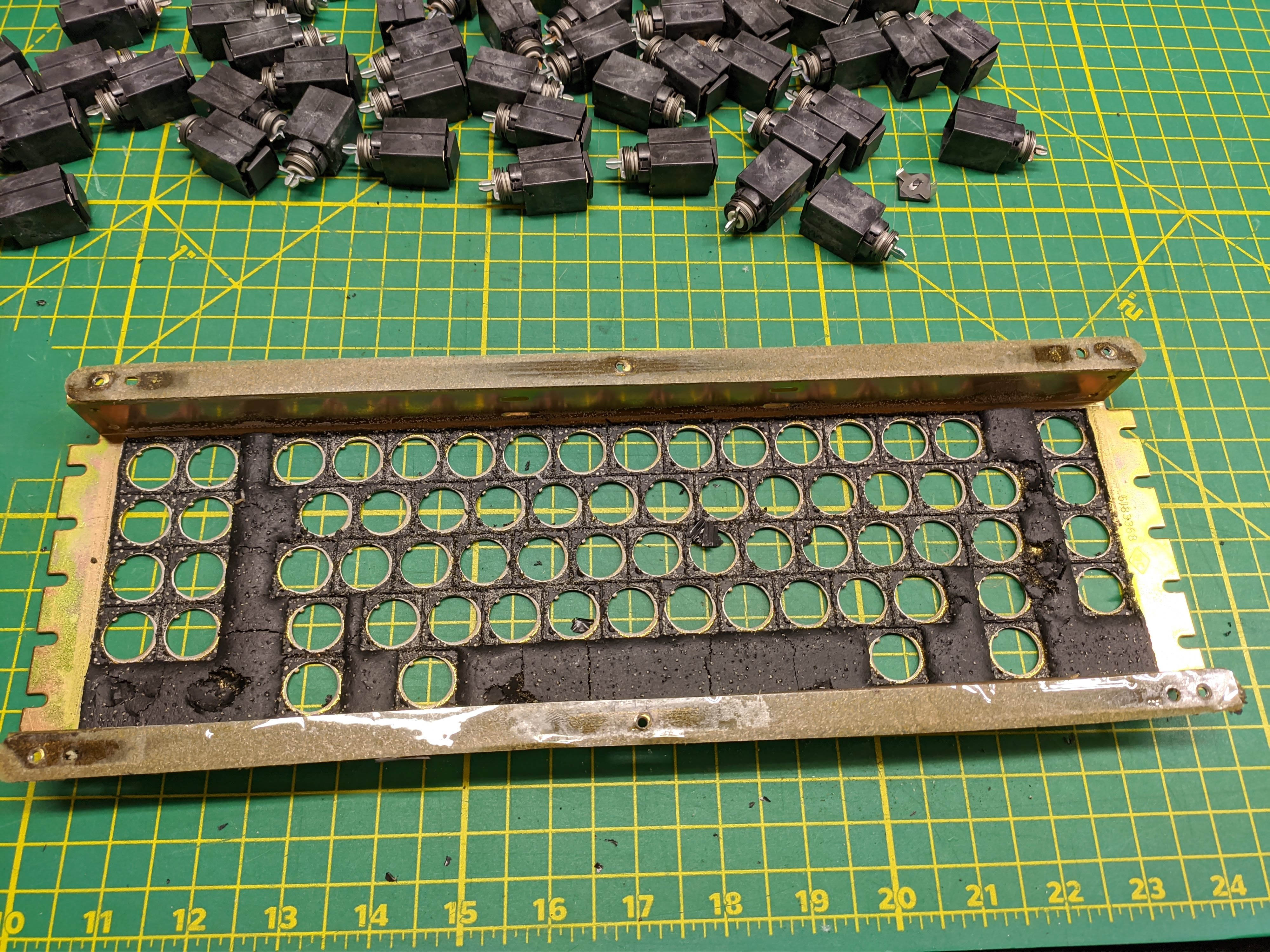
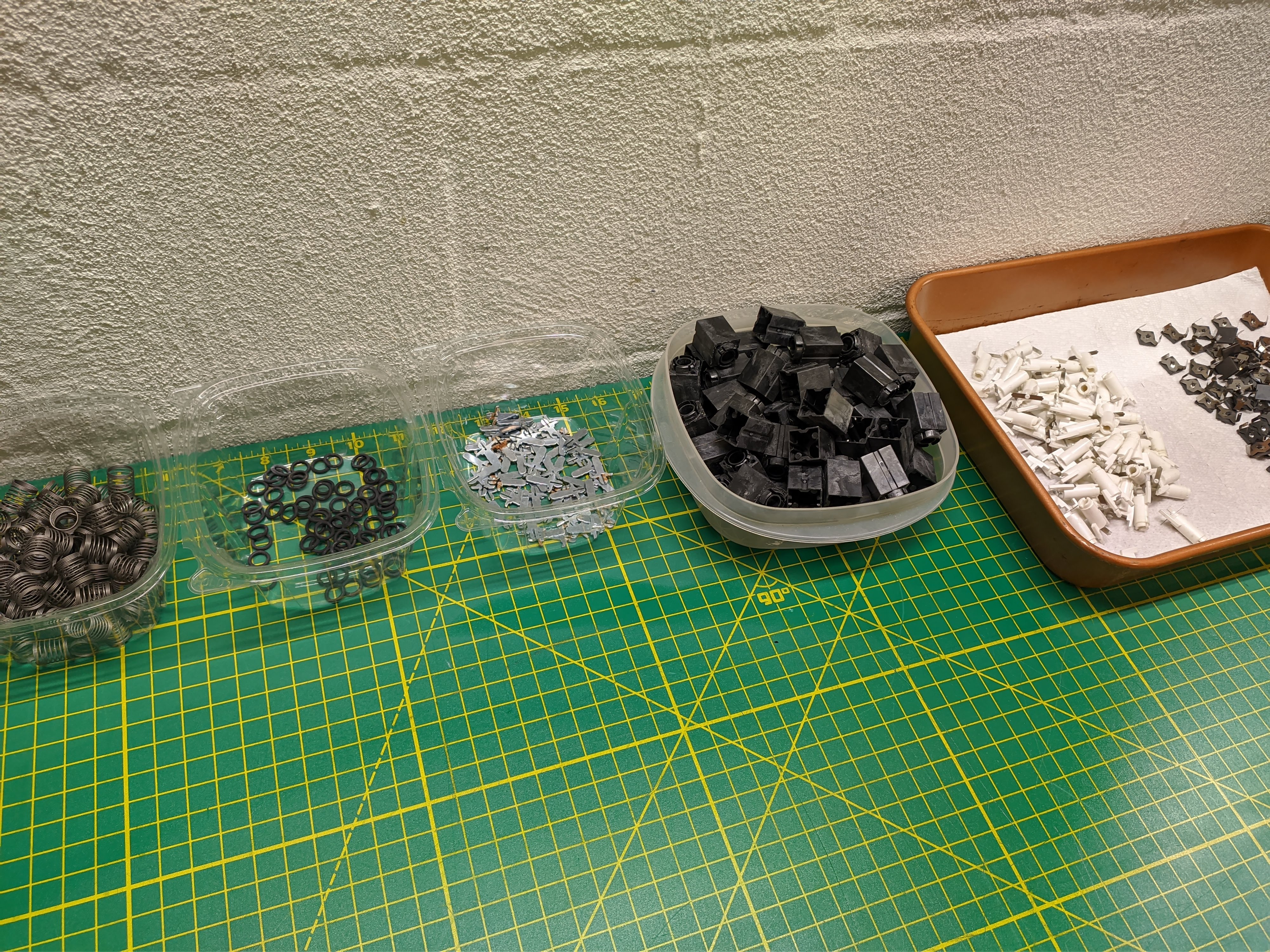
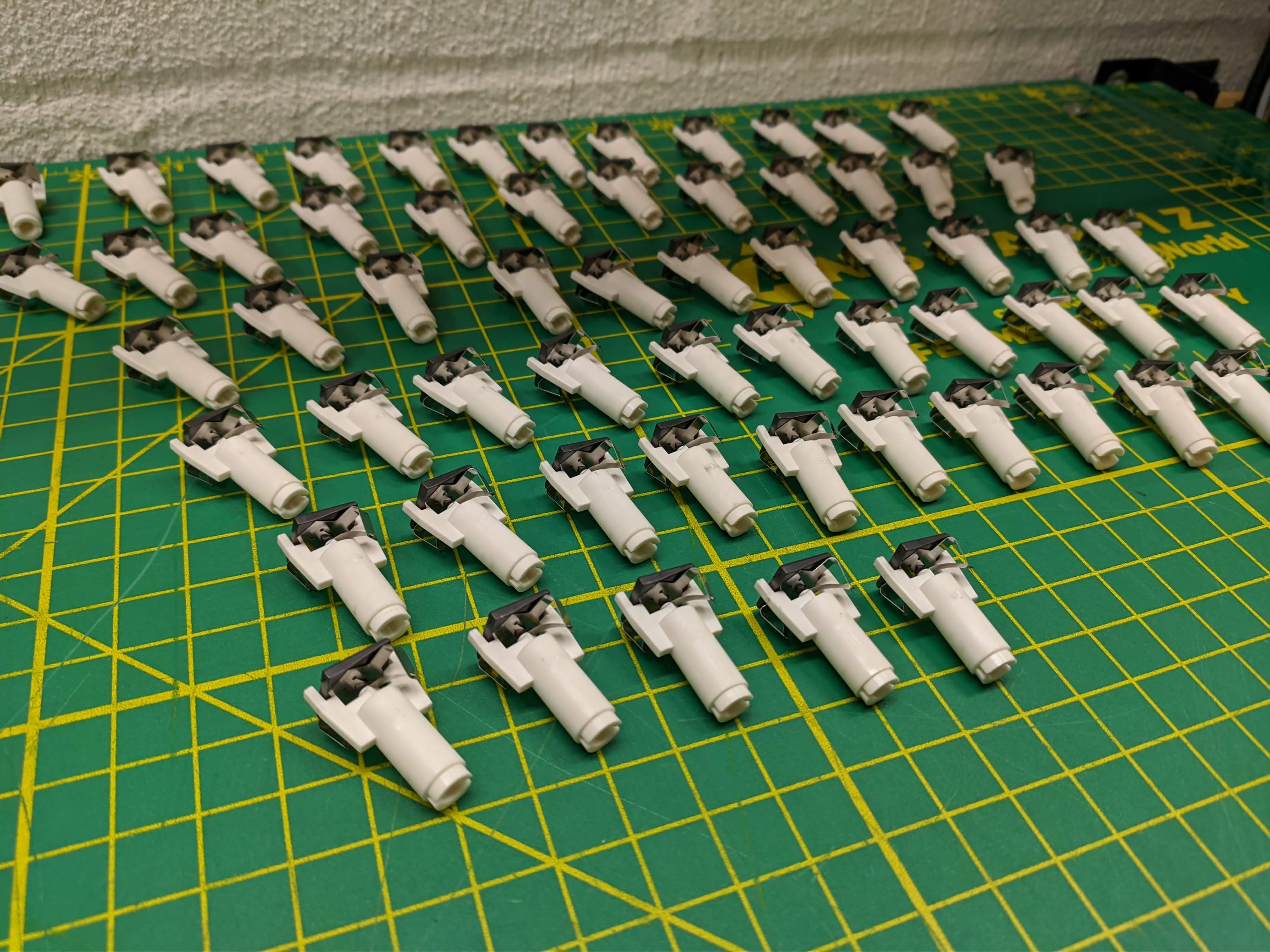
All but one of the switches were in great shape. The thin area around the melt rivet seems to be a weak point since I've seen the same failure on another beamspring. Fortunately the spacebar has a dummy switch with an intact and unused beam that I could steal.

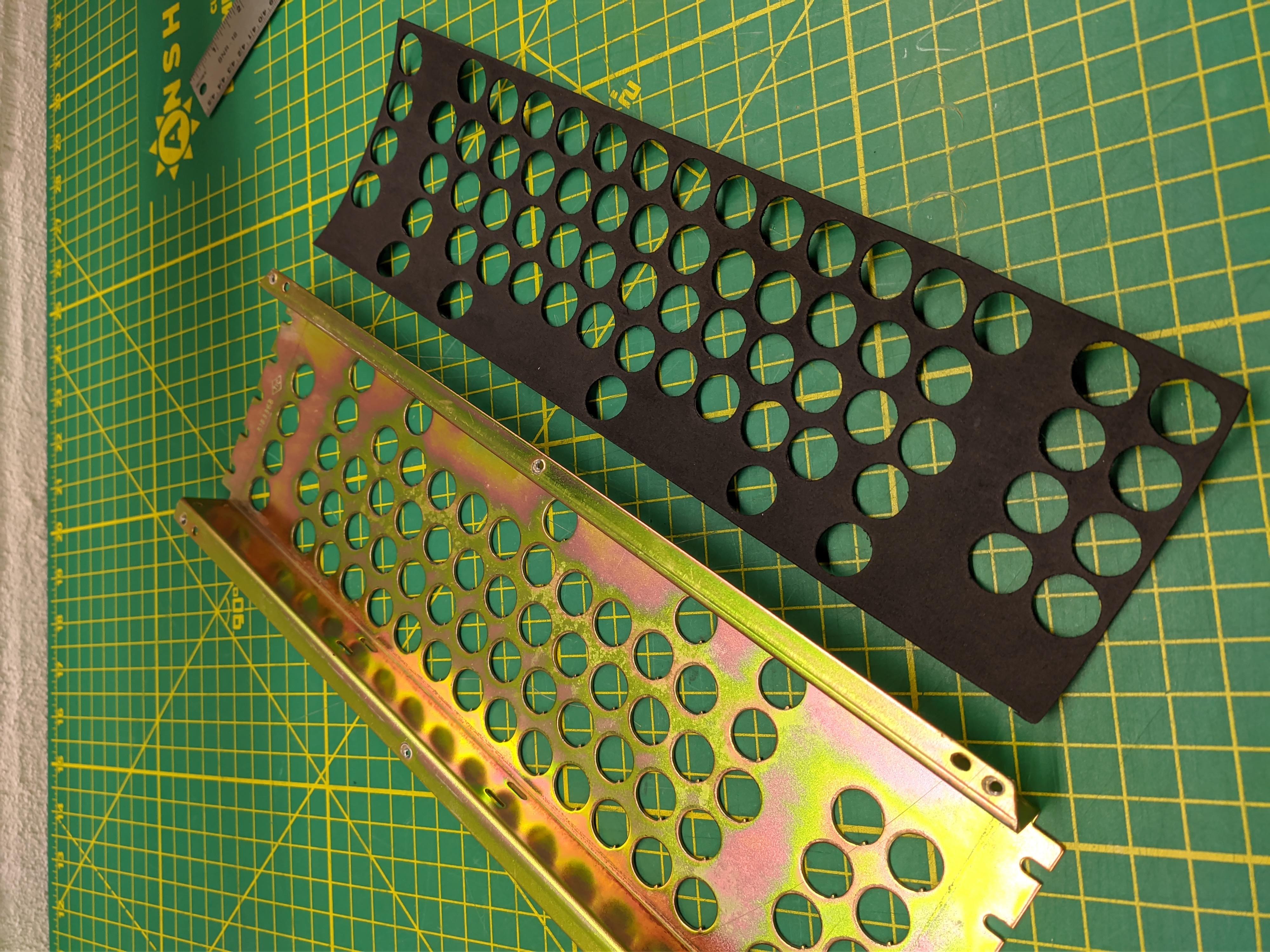
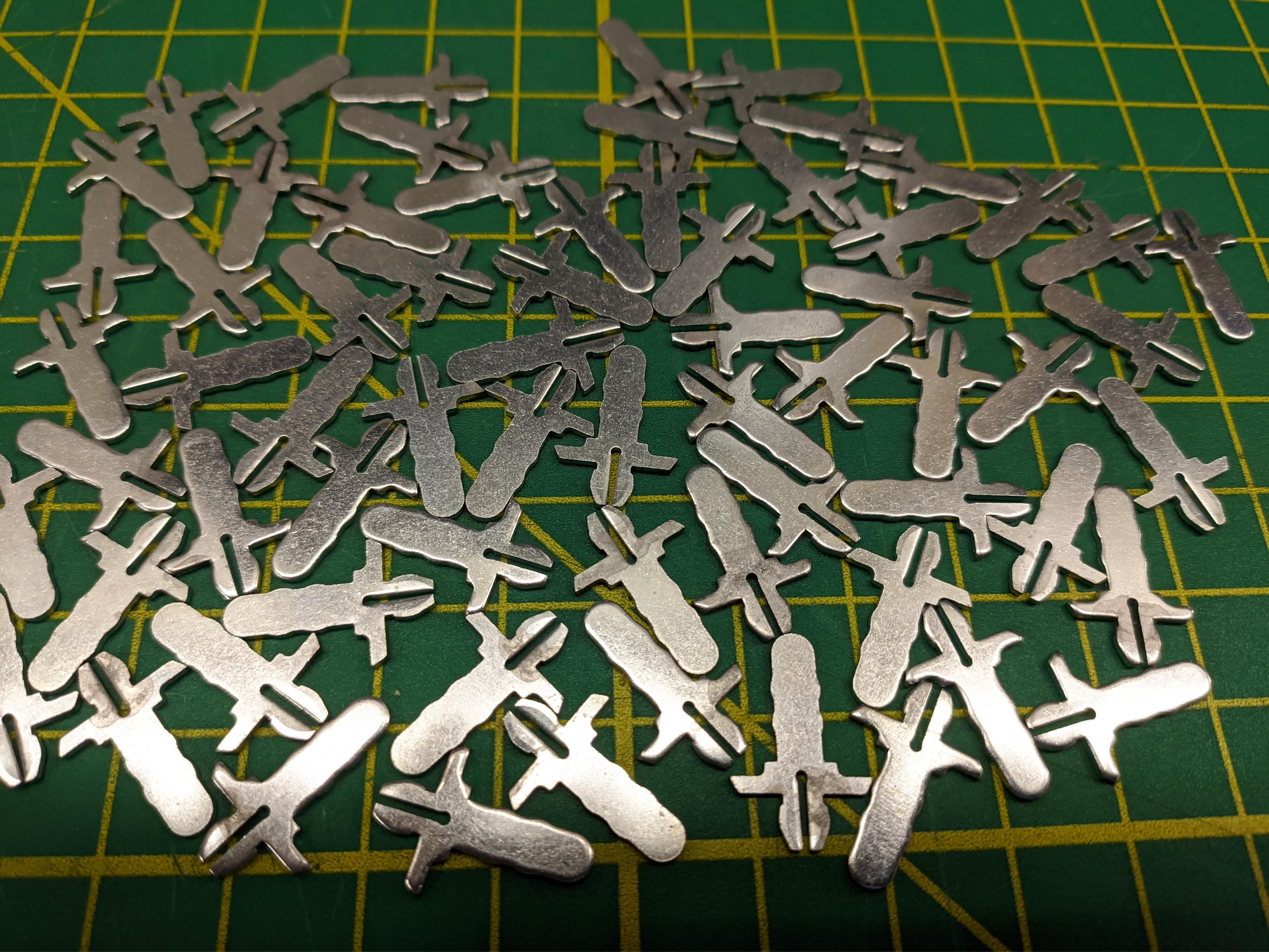
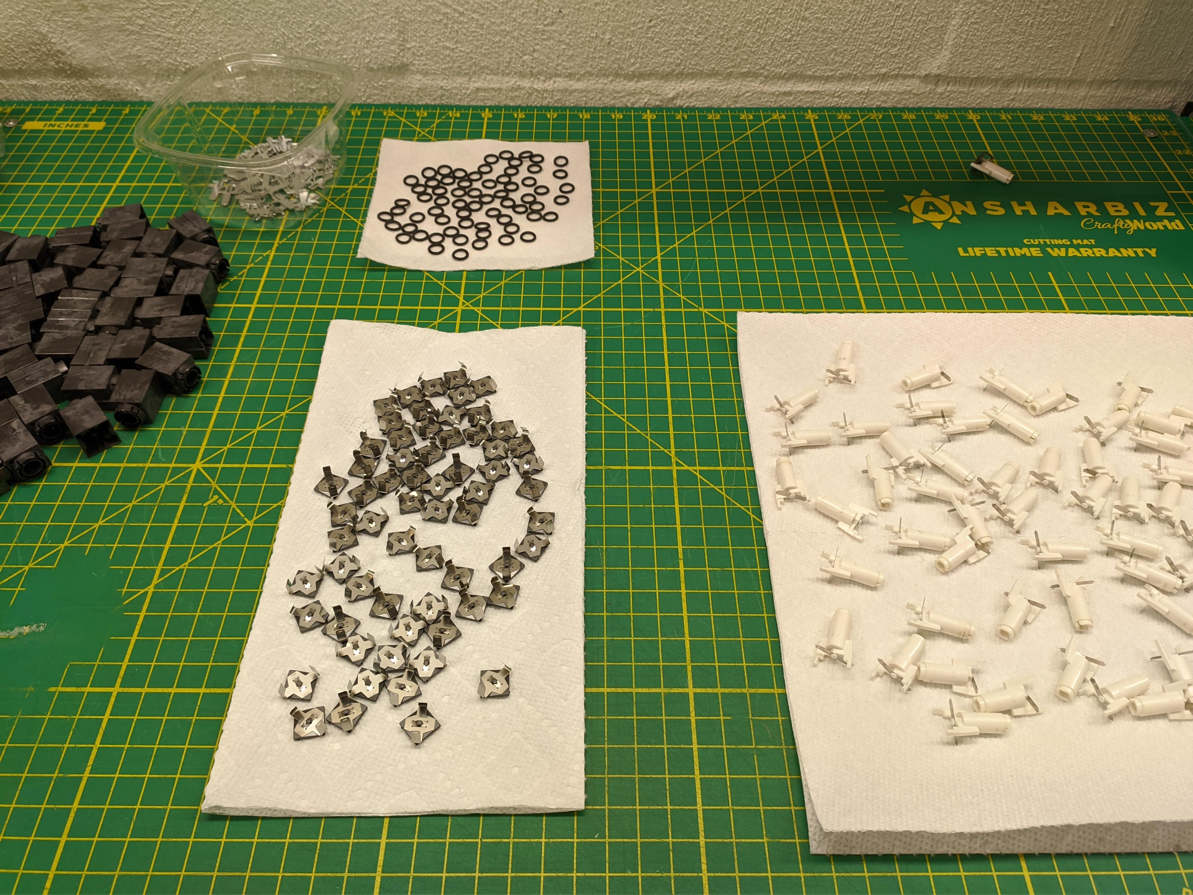
Switch housings and keycaps were cleaned with a soapy water soak and an ultrasonic bath. Stems and fly-plates were rinsed with isopropyl alcohol. Stem inserts and springs were given a treatment of rust remover, cleaned with isopropyl, and then treated with a platic safe rust preventative coating. The metal parts were cleaned of the bulk of the foam with hot soapy water. The remaining backing plastic was removed with a heat gun and a plastic scraper. Finally any remaining adhesive on the metal was cleaned with goo-remover before being rinsed and washed with more soapy water and isopropyl.


The PCB was cleaned with some anti-static brushes and then washed with isopropyl. The plastic spacer strips were cleaned of the old glue using more isopropyl and then re-backed with some acid-free adhesive tape. Fresh foam was cut using a leather punch and the board reassembled without a hitch.



CRT display
The CRT assembly is manufactured by Motorola and likely uses a Sylvania tube. It's part of the Motorola XM series; larger versions of this display were apparently used in arcade machines of the same era. Thanks to Arcade Museum I was able to track down a technical repair manual for it.

The monitor itself is driven by a standard composite video signal, the same as the once ubiquitous yellow RCA connector. Connecting up an old Raspberry Pi shows very promising results. The display goes from bad overscan to a solid, stable rectangle. That indicates that the sync separation circuit and both deflection circuits are more or less functional.
Unfortunately, no amount of turning brightness/contrast dials was able to get anything other than a blank or solid white screen to appear. Basic stuff like cleaning the adjustment potentiometers had no effect. With the help of the repair manual and an oscilloscope the video signal was traced from source all the way through the amplifier circuit. It propogated just fine at every step through transistors and various filters, making it all the way up to the point of entering the CRT itself. However, there's a final and vital component in the circuit. The video amplifier circuit effectively results in a pull down signal on the cathode. The line it pulls down is pulled up to ~150V through a 3.9kOhm resistor - that resistor measured open circuit.
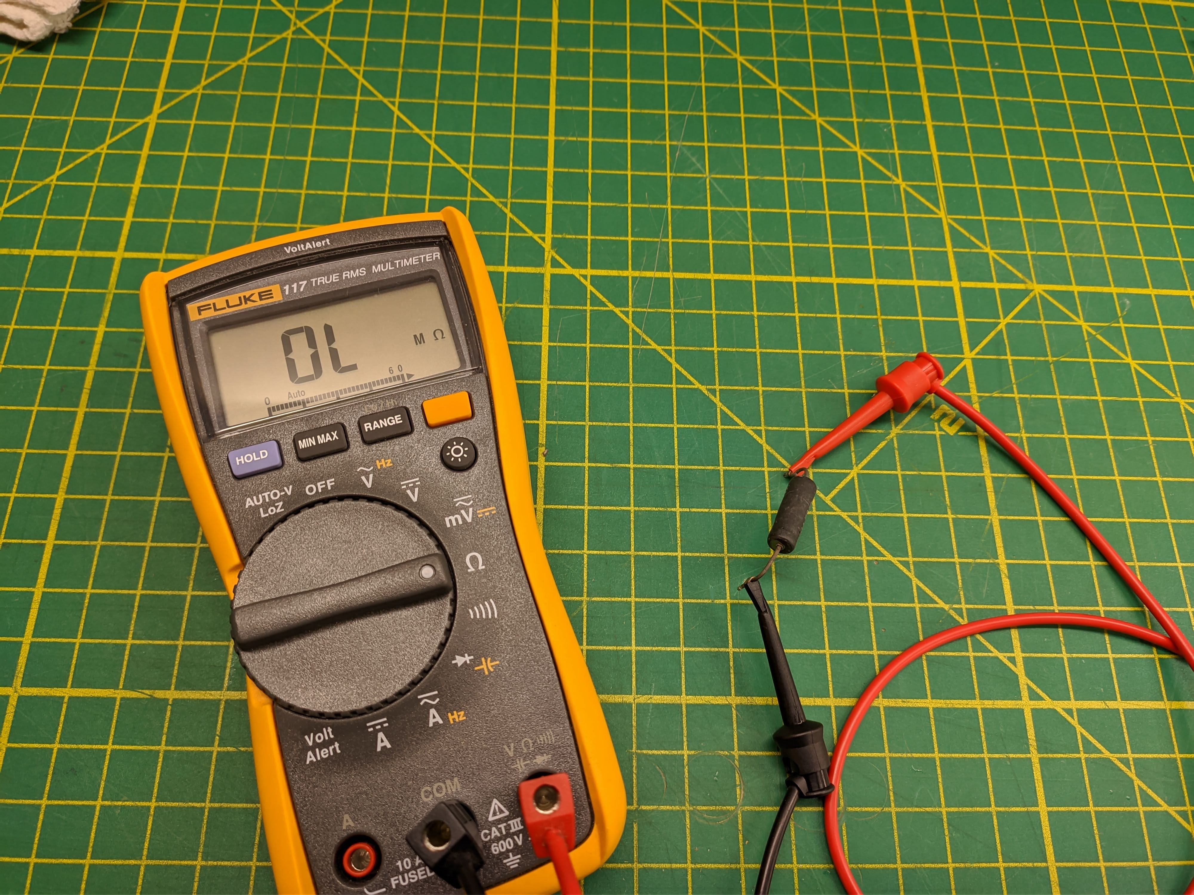
Without a working pull-up resistor the line was floating between 0 and a couple volts, nowhere near enough to get output on the CRT. Putting in a modern replacement resistor yeilds the correct floating voltage and an image on the display for possibly the first time in decades. Photos don't do justice to just how bright this display can get if you crank it up. Contrast is excellent and there's very little burn in. With a few adjustments to the yoke and linearity pots I got the image looking about how it should. Due to it being an interlaced display it looks quite weird in photos; the camera only picks up every other scanline.
Reverse engineering
As you probably noticed by now, there's not a whole lot actually going on inside the terminal itself. I've seen this setup referred to as a 'mindless' terminal since it's even dumber than a dumb terminal. The card part of the 4979 pair seems to be responsible for almost all of the terminal functions. The card would communicate with the Series/1, maintain a character buffer, parse keyboard info, and generate a composite video signal. The cable leaving the back of the 4979 is basically a straight passthrough of composite video and whatever is on the mysterious keyboard connector.
Bearing a close resemblance to the 66-key IBM 3277 keyboard I dug up some 3270 docs and started investigating. I've come to the conclusion that apart from the layout and internal connector there's likely not a whole lot in common between the boards. I'd have to start from scratch.
After arbitrarily defining pin numbers and buzzing some stuff out with a multimeter I determined which pins were for power, shield/ground, and found a handful that should be for data. Hooking them up to a logic analyzer and giving the board power showed a pretty neat pattern of frequency halving clocks. Pressing a key stopped the clocks for the duration of the press.
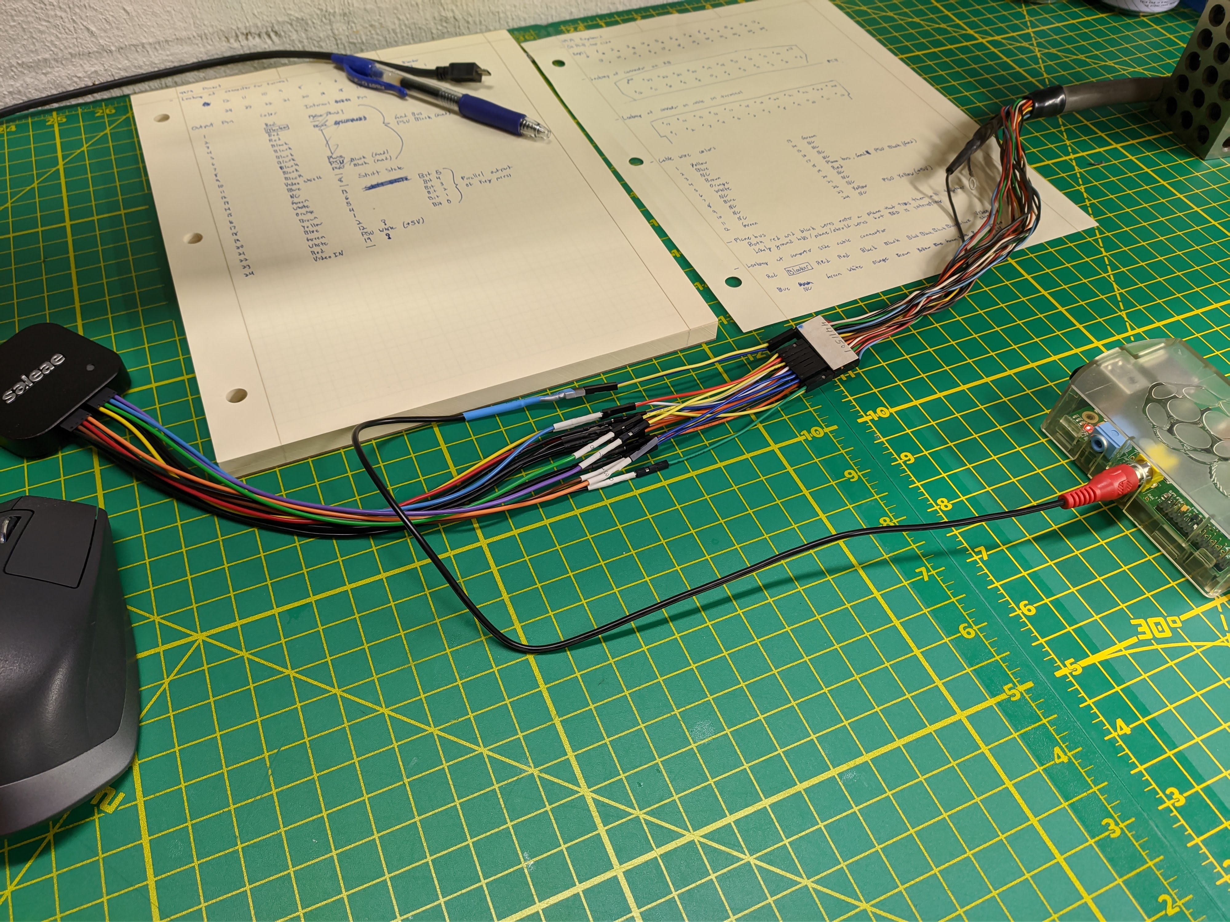
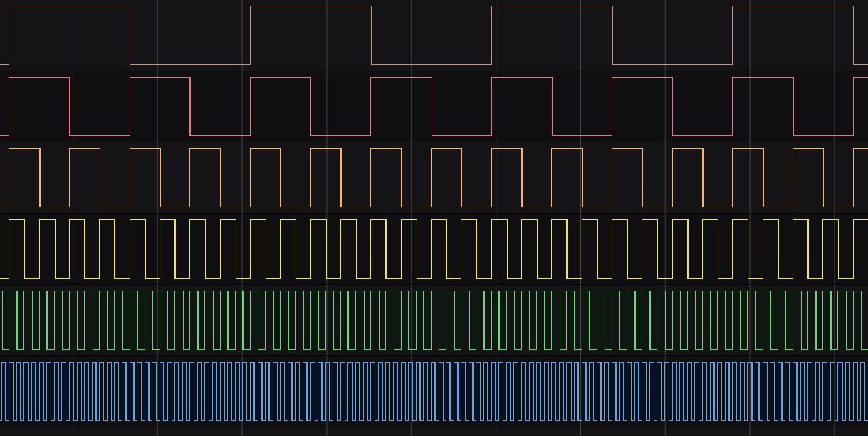

Eventually I noticed that each key stops on a unique combination of high/low values every time. I realize what I was actually seeing was the individual bits of a binary number counting up. Some more probing and messing around with pull-up/down resistors found a strobe signal and shift state line. The protocol was cracked - it's a parallel output bus with strobe. You just use the strobe signal to gate out the whacky binary counting.
On the falling edge of the strobe signal you read in the value of the output bits and shift line. This gives you a 7-bit number (or 6-bit with shift) that corresponds to the key pressed. The strobe signal is held low the entire duration of a key press. Pressing a second key does not result in the output changing until the first key is released. It's therefore a 1KRO protocol not including shifts.
Shift state line is changed by any of 3 keys. The left and right shifts function as expected, the line is high when they're held, low when released. The caps lock key is 'secretarial' style. Pressing it will set the shift line high. Pressing caps lock again while it's already enabled doesn't do anything. It only goes low when one of the other shift keys is pressed and released.
The output bits don't correspond to the legends on the keys but rather their position on the keyboard matrix. After punching every button and recording their values I generated the full keyboard map. The 6-bit bus supports up to 64 keys ($2^6). The keyboard has 66 but 3 are on a separate shift line so it's effectively a 63-key. IBM shorted us one key, there's nothing at matrix position 000011 (3).

Pinout
Looking into connector on the Series/1 card:
13 14 15 16 17 18 19 20 21 22 23 24
1  2* 3  4  5  6  7  8  9  10 11 12
*Position 2 is the key blocker
| 4979 Pin | Wire Color | Function | 32u4 pin | Raspberry Pi |
|---|---|---|---|---|
| 1, 3-11 | Black, red | GND | GND | |
| 12 | Black | Copmposite video shield | GND | Composite outer barrel |
| 13 | Blue | Shift state | PD0 | |
| 15 | Green | Keyboard bit 0 | PD1 | |
| 16 | White | Keyboard bit 1 | PD2 | |
| 17 | Orange | Keyboard bit 2 | PD3 | |
| 18 | Brown | Keyboard bit 3 | PD4 | |
| 19 | Yellow | Keyboard bit 4 | PD5 | |
| 20 | Blue | Keyboard bit 5 | PD6 | |
| 21 | Green | Keyboard strobe (use pull up) | PD7 | |
| 22 | White | +5Vdc from 4979 internal PSU | ||
| 23 | Red | ? Possibly "ready" | ||
| 24 | Black | Composite video input | Composite inner pin | |
| 2, 14 | Not connected |
Converter
The keyboard operations could be handled by the Raspberry Pi GPIO but, in the interest of simplicity, I chose to base the converter on a Teensy 2.0 (32u4) running QMK. QMK allows you to substitue the normal matrix scanning operation with your own callable function. That function modifies an array to update the state of any pressed keys, simple enough. QMK will apply whatever layered maps are programmed in, and determine what needs to be fired off over USB. There'd normally be a debouncing operation in there but I have it disabled since it's handled in hardware by the keyboard controller.
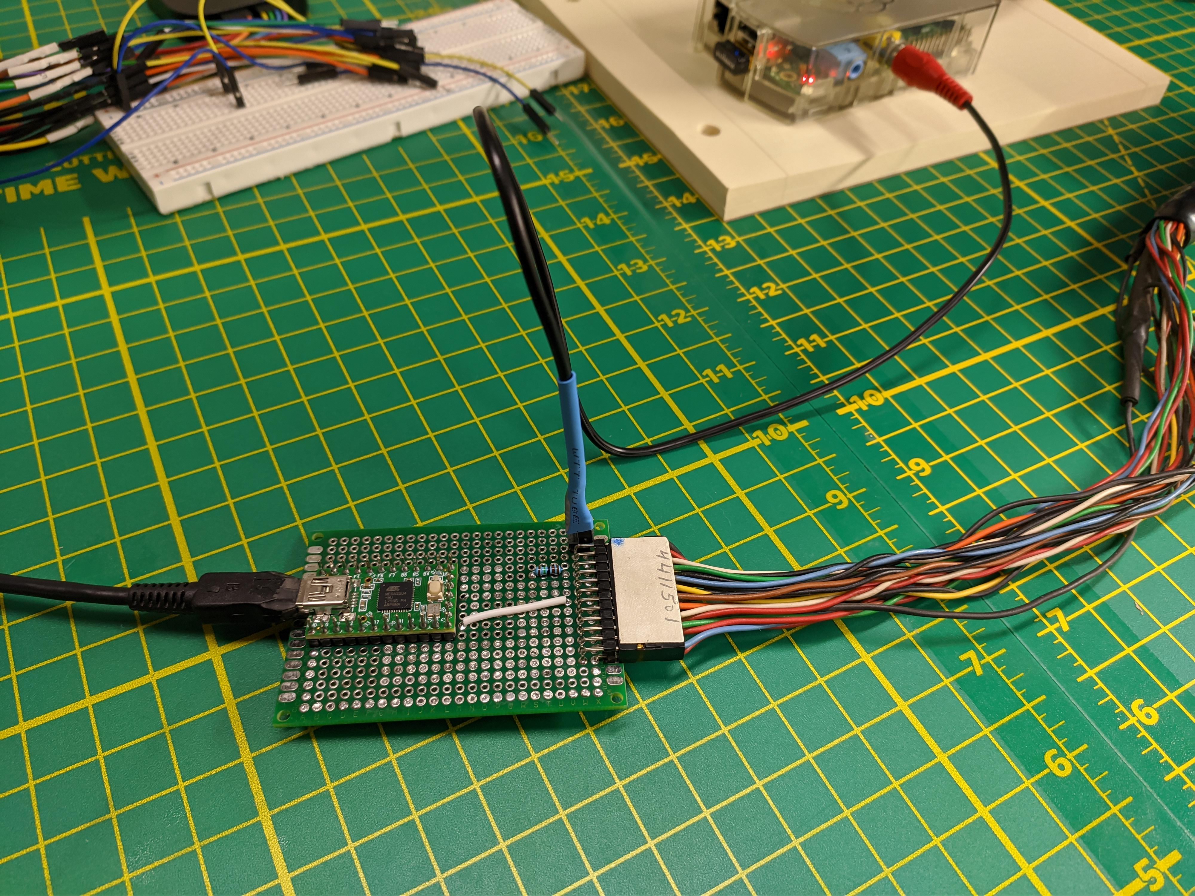
Being a parallel protocol I decided to try out a feature of the 32u4 called port operations. There's some slightly hidden registers that can be written to and read from that control all pins on the port in one go. I have the keyboard connected to PD0-7 so reading PORTD will read in all 8 bits at once into a single 1 byte variable.
The message from the keyboard can only contain effectively two keys, shift and one 'other' key. 'Other' being any of the non-shift keys on the board. The 'other' key needs to be gated by the strobe signal. The matrix handling process goes as follows:
graph
    A[Read PORTD]
    B{Shift bit high?}
    C{Strobe low?}
    D(Add to pressed key list)
    E(Decode remaining 6 bits)
    F(Shift is pressed)
    A-->B
    A-->C
    B -->|Yes|F
    C-->|Yes|E
    E-->D
    F-->D
QMK can figure out the rest.
The keyboard originally wouldn't be used to type both lowercase and capital letters from what I can tell. The shift key would instead change between typing capital letters and typing the second symbol on the keys. I wanted to keep this sort of behavior while also having the ability to use it like a more normal keyboard. I set up the layers such that the base layer is a more or less standard typing experience. The 1KRO limit means you do need to use modifiers (excluding shift) as one shot keys. You press and release CTRL, then press and release A, the computer sees you pressed CTRL+A. One of the keys on the side functions as a layer switch which swaps the keyboard over to a more correct mapping. In that mode it types in single case (there's still a caps lock key) with shift changing between the primary and secondary legends on the keys.
Conclusion
Connecting everything up to a Raspberry Pi gives you pretty much the full experience of using the terminal. Granted it's running Linux instead of IBM's EDX, you do get a fair bump in compute power to make up for it. That's not surprising since a base model Series/1 had 16KB of RAM and ran at 1.2MHz; it's hardly a match for a graphing calculator. I don't know exact numbers but I suspect the Pi is more power efficient than the Series/1 as well. Conveniently, the terminal actually supplies enough power over the cable to run the Raspberry Pi and Teensy.

