Arduino simple Visible Light Communication - jpiat/arduino GitHub Wiki
**The code for the emitter and receiver can be found at https://github.com/jpiat/arduino. **
Visible Light Communication (VLC) is a way to transfer data using visible light. There are multiple application such as
- Data streaming : Use your ceiling lights to stream music/video to your devices
- Positioning : Each ceiling light of a building transmit its own position, it becomes easy for the receiver to determine where it is in the building (cheap and easy)
- Wireless communication within a defined area : Light does not go through walls and power is weak outside the focused zone.
This example uses VLC basic principles to create a low performance simplex communication between two arduinos using only
- Two clear LED (either red, green, blue not white), RED proved to be the best option
- A 1Mohm resistor
- A 120 ohm resistor
#Using the demo
On the emitter side, you'll need a LED connected in series with the 120ohm current limiting resistor between digital output 2 of the arduino and GND. On the receiver side you'll need to have a a LED with the anode connected to Analog input 3 of the arduino and cathode connected to GND. You'll need to put the 1Mohm resistor in parallel with the diode.
Load the receiver code on the receiving arduino and emitter code on the emitter arduino. In default mode the emitter will emit "Hello World N " with N counting. To see the received character, opens an arduino terminal for the receiver at 115200bauds and try to align the emitter and receiver. Once aligned you should see the aforementioned sentence in the console.
The emitter can also be configured to output chars received on its serial port by uncommenting the line :
//#define TRANSMIT_SERIAL
In this mode, the transmitter will send the character sent through the serial port in packet of 32 bytes or whenever it encounter the character '\n'.
Demo underlying concepts
Emitter side
In VLC its not possible to just serialize the data to transfer and use each serial bit to drive a light source. Doing so would result in a variation of the light source that can be seen with the naked eye and even with fast transmitting speed (and perceived light intensity would depend on the data). A simple way to encode the data bits that does not affect the perceived lighting is Manchester encoding of the bits. In Manchester encoding a bit is not represented as a steady state of the signal but as a variation. For example a bit with value one will be encoded by the signal going from the low state to the high state and a zero will be encoded by the signal going from the high state to the low state. For a light source this mean that the light quantity averaged over a period of time will no vary over time (for a light source blinking faster than 25Hz, the eye acts as a low-pass filter that average the light quantity).
In this demo the data to send is a just serialized (with a start and a stop bit) and Manchester encoded to drive the LED. As a consequence the LED appears to be ON all the time for the user. The data is sent with a symbol rate of 1200baud which correspond to a bit rate of 600 bit/s. Depending on the led quality and ambient light, the baudrate could be increased (don't expect gigabits).
Receiver side
The receiver in this demo is just composed of a LED wired between analog input 0 and ground. A parallel resistor of 1Mohm is added to the LED to avoid capturing noise on the analog input. Using a LED to receive light is possible. In this case the LED will generate a small current which in turn generate a voltage thanks to the LED serial resistor and the ADC input impedance. The interesting things is that the LED is very selective, meaning that a blue LED will only capture blue light (same for red and green). A white LED won't work as a white LED is just a blue LED with phosphor coating.
In this demo the voltage of the LED is captured by the ADC four time faster than the emitter rate. The voltage is averaged over time to compute a threshold to discriminate high and low state of the incoming signal. This threshold is used to binarize the signal and then decode the Manchester encoding. The serial signal is then decoded (detection of start and stop bit) into a byte stream.
Frame format
To help with the synchronization of the receiver and emitter, the data to send is encapsulated into a frame. This frame is composed of a synchronization preamble (0x55) that helps to compute the binarization threshold. A 0x5D then breaks the synchronization (helps detecting the manchester encoding phase), and a STX (0x02) symbol indicate the start of the frame. A sequence of maximum 32 bytes then follows and a ETX (0x03) ends the transmission. This naive frames helps with synchronization recovery but a better frame model would be to add a CRC for error detection in the frame.
Performances
The code was tested with multiple configurations
- Blue clear LED : communication speed ~600bit/s, communication distance ~7cm
- Red clear ultra-bright LED : communication speed ~600bit/s, communication distance ~30cm
- RGB led with only red channel used on reception : communication speed ~600bit/s, communication distance ~4cm
- 1 Watt RGB led bulb : Communication ~1kbit/s, communication distance ~3m line of sight (with receiver properly oriented).
Performance greatly depends on the following.
- Max achievable bitrate depends on LED quality for emission and reception (parasitic parallel capacitor)
- Distance depends on emitter/receiver alignment if the LED is focused. A highly focused LED will allow greater distance of communication but will require proper alignment of receiver and emitter.
- 5050 RGB LED does not have a highly focused beam resulting in short distance of communication (also because we direct drive the led using the Atmega outputs at 20ma)
- Diffused LED won't work at all
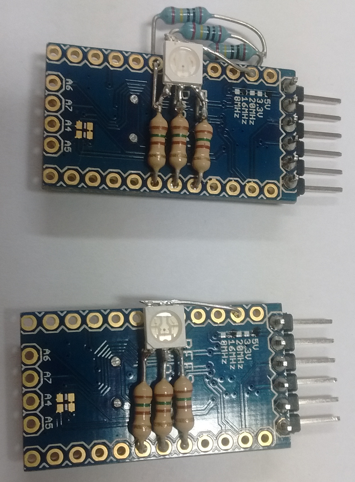 Image of the RGB LED test setup using arduino pro Mini (clone). Only the top module can be used as a receiver.
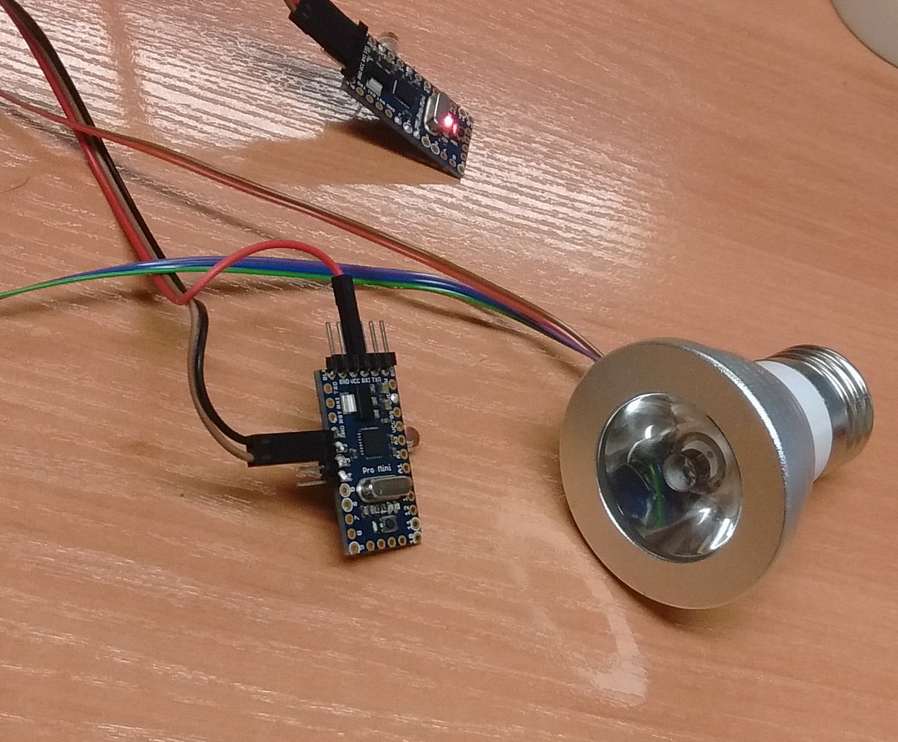 _Image of the emitter pro mini driving a modified RGB 1 watt led bulb
How to improve
- Use amplifier circuit on receiver LED
- Use MOSFETs to drive the emitting LED to achieve higher emission power
- Add CRC code to the data frame for error control
- Improve manchester decoding to detect rising-edge/falling edge instead of thresholding (compute derivative of signal)
- Test higher bit-rate (could work depending on the LED and if a amplifier circuit is used on the LED)
- Use the three channel of a RGB LED to encode data (can achieve 3x the bandwidth)
- Current Manchester encoding/decoding limits the duty cycle of the signal to 50%. Improving encoding/decoding scheme would allow to also set the lighting brightness.