RC Airplane Build - joshuarothfuss/projects GitHub Wiki
Since I was 8 was have loved flight. Early in 2017 I bought a RC airplane, it was fantastic but I wanted better. Store-bought is fine, but I really enjoy making things myself and fully customizing them to my vision. There have been 4 prototypes so far.
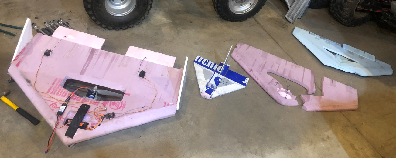
Versions 1—4 from Right to left.
Version 2 Vertical Climb Version 2 Take Off
Tools/Skills Used
- Band Saw
- Razor Blade
- FDM 3D printer
- Fusion 360
- Drill
- Hotglue Gun
- Orbital Sander
- Belt Sander
- Soldering Iron
- Wire Foam Cutter
- Basic Hand Tools
- Electrical Analysis
- 3D-Modeling
Version 1 - Flying Wing
This was a large learning experience. It flew exactly once before wrecking and damaging the nose.
- Hardware: The structural portions of the design were made with foam and hot glue. The control system was a spectrum A636 6ch receiver paired with a Spectrum transmitter. The receiver interfaced with 2 generic 8g servos, and a 40amp ESC and Motor.
- Design:
When setting out to make an airplane, the flying wing was chosen over a more traditional airframe due to multiple factors:
- production time - In order to prototype quickly, it was ideally makeable in the 3-5 hour range.
- simplicity - In order to test quickly it needed to be simple and easy to repair.
- intrinsic strength - Having all forces in the same 2D-plane made wrecks less catastrophic.
- increased wing real estate - The goal was to be able to carry payloads, a large wing was ideal.
- cost - electronics and propellor placed central to the wing, reducing exposure of $$$ parts
- Construction: This version was made exclusively with foam. It was relatively strong and easy to shape. An orbital sander and 60-grit sandpaper was use to shape the wing. This was a long and messy process that was improved in future versions. The control surfaces (2 elevons) were also made with foam. They were attached with tape in a configuration to allow for a hinge motion. Short sections of steel wire were used to attach the servo horns to the elevons. No landing gear was attached. No tail was attached. Fusion 360 was used to make a motor mount that would allow the motor/propeller combo to be glued to the frame.
- Performance: It made a total of one flight. The power-to-weight ratio was excellent and allowed it to gain altitude quickly. The lack of any vertical stabilization was it's down fall. The Roll axis was controlled sufficiently, but with no Yaw control, it started to spin in a way that wasn't recoverable. The nose of the Airplane was irreparably damaged. Due to foresight in wing design, no electronics were harmed.
Version 2 - Adding a Tail
This was a huge milestone in the version history. It would make upwards of 50 flights and allow for the tuning of many aspects, including: center of gravity, elevon trim, wing shape, thrust vector (relative to airframe) and other subtle parameters.
- Hardware: This was exactly the same as version 1, see version 1 hardware section. All of the electronics were stripped and used in this design. Some additional foam was used to solve stabilization issues.
- Design: The benefits of the flying wing design (as discussed in version 1 design) were paying off. The biggest addition made was the addition of a total of 3 vertical stabilizers. 1 on either side of the wing and 1 on the underside of the airframe that doubled as a landing skid. The airframe as a whole was also elongated to decrease pitch (angle of attack) sensitivity.
- Construction:
Everything from version 1 construction was replicated with 2 major changes.
- A resistive-wire-based foam cutter was made and used to quickly get the wing to the rough shape.
- Additional hot glue and foam were used to add the vertical stabilizers. The orbital sander was then used to finish the shape.
- Performance: This airframe was significantly better. It made 50+ flights (approx 3 hours of flight time). It proved capable of lifting quite a bit and taking wreck after wreck. Having a reliable airframe allowed the reliability of other systems to be tested. For instance the battery mounting system (see image below), and the elevon fixation. In the end, it was a catastrophic airframe failure that necessitated Version 3.
The battery mount failed and the battery fell into the propeller.
The final result of Version 2
Version 3 - Small and Fast
The previous version was good, but slow. The goal for this one was 60+ mph and to prepare for a 100mph airplane. This airframe made 3 flights before it was retired due to being totally controllable.
- Hardware: This airframe was made out of sign-board, hot glue, wire, and some foam. The electronics stayed the same.
- Design: This airplane was design to have minimal drag. Because of that, a narrow wing was made. Foresight also prompted that the frame should be long for high-speed stability. A single vertical stabilizer was mounted in the center of the wing.
- Construction: It was made primarily out of sign-board, which was cut by creasing it with a razor blade and then splitting it. The motor was mounted facing forward off the front of the airplane. This exposed the propellor and the motor, making them very venerable to damage. The elevons were also made out of sign-board. They were made huge in comparison to the wing for control during slow flight. A smaller propellor was used, but this propellor had a significantly steeper pitch. When calculated using reasonable rpm, the theoretical airframe speed was 147 mph.
- Performance: This airframe was terrible. It was impossible to control at any speed. Everytime the throttle was adjusted, the roll axis would become impossible to stabilize (See linked video of flight #2). In the process of making 3 flights, it broke the propeller, striped 2 servos, and snapped the motor shaft. What was left of version 3 was striped of parts and Version 4 was started.
Version 4 - Bigger is Better
This was essentially a recreation of what worked with a few tweaks. To date (3/20/2023), it has made 20+ flights. These flights have furthered tuning aspects of discussed in the opening of Version 2. It is larger than all previous airframes to allow for a larger lifting capacity. See the photo at end of Version 4.
- Hardware: Because of the equipment casualties in Version 3, Version 4 got some new components. 2 25-gram servos were used. Along with a 670w motor and 60-amp ESC. The propellor size was also increased up to 14 inches.
- Design: This airframe is the same as Version 2 with 2 modifications. The foam that was used was twice as thick, and the airframe is a couple of inches bigger in every direction. The goal being bigger and stronger.
- Construction: The airframe was shaped using the previously built foam cutter and honed with 60-grit sandpaper. A 14-inch propellor with a medium pitch was used for good torque and still decent speed. The 3D-printed motor mount that was used in all previous versions, was replaced with an Aluminum one due to a new motor/motor-mounting style, and strength. The additional thickness of the airframe allowed the battery and some electrical components to be placed inside the frame.
- Performance: This airframe was significantly better than Version 2, and exponentially better than Version 3. Version 4 has made 20+ flights (approx 1 hour of flight time). It proved capable of lifting more than Version 2. It currently has 5 mounting points on the bottom of the wing for rocket engines, model rockets, live stream camera/s, and bottle rockets. Another project that I am working on is a remote ignition/deployment system for onboard rockets and servos. (See the page on Remote Ingitor)
Size comparison of all airframes. V4 (on bottom), V2, V1, V3 (on top)