IMU SPI IP Core - jofranco/multi-rotor-on-FPGA GitHub Wiki
Overview
The IP AXI Quad Serial Peripheral Interface (SPI) core connects the AXI4 interface to SPI devices. For our project we used the Digilent Pmod Nav with the LSM9DS1 chip which provides 9DOF for accelerometer, gyroscope, and magnetometer. We instantiated and communicated with the Pmod Nav through SPI which naturally led us to leverage the AXI Quad SPI in our Vivado project which is synthesized and implemented in the Programmable Logic (PL). For our project we used 4-wire SPI communication setting up the AXI Quad SPI as a master and the Pmod Nav as a slave. The AXI Quad SPI is able to support up to 32 slaves and provides the interface to automatically enable/disable slave devices or manually perform the slave selection.
Interface
In order to transfer data between the AXI Quad SPI and Pmod Nav, there needs to be external ports configured for the AXI Quad SPI which is done on the Vivado block design and mapped through the constraints file. See figures below for interface details.
Vivado Block Design
Vivado Block Design: AXI Quad SPI
Vivado Block Design: Contraints file
The AXI Quad SPI is configured for 4-wire SPI communication these wires comprise of Slave Select (SS), MOSI (Master out/Slave in), MISO (Master in/Slave out), and SCLK (Clock).
Function
The purpose of the AXI Quad SPI is to provide a working SPI core without having to worry about the Xilinx Advanced eXtensible Interface (AXI) protocol for Intellectual Property (IP) cores. The SPI is a synchronous data bus since there are two separate lines for data and clock which keep them in sync. The clock is an oscillating signal that tells the receiver (can be MISO or MOSI) when to sample the bits on the data line. The SPI bus is a "full duplex" meaning that you can transmit and receive data at the at the same time. Using the SS you can talk to different sensors, as follows:
SPI 4-wire communication
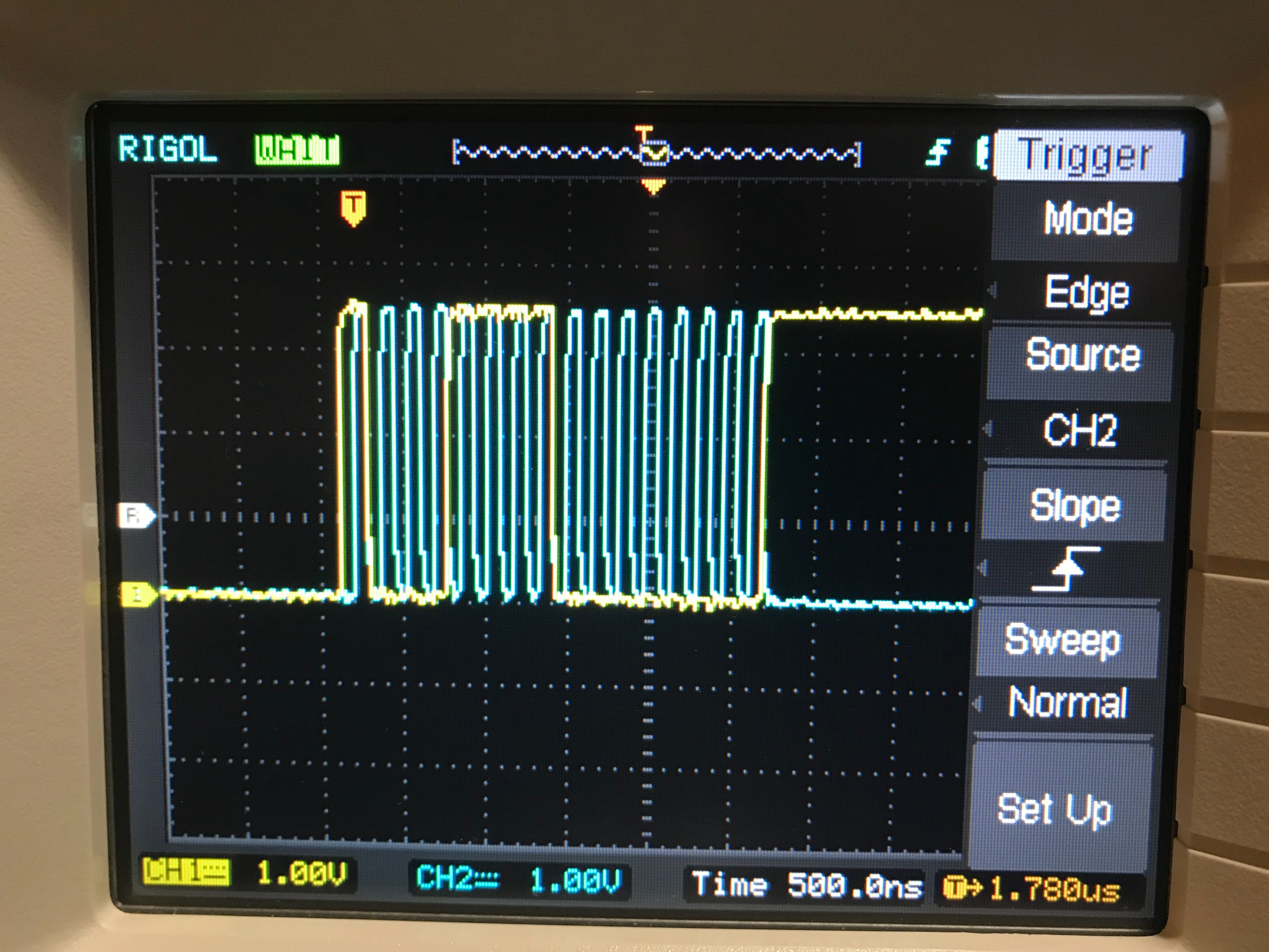 The figure above shows the CLK and MOSI line. MOSI line transfers 16 total bits, 1 bite for read/write, 7 bits for address, and 8 bits for data. This image from the oscilloscope is read to the
 WHO_AM_I register on the LSM9DS1 chip. Reading from WHO_AM_I register is part of the state machine for the SPI Driver in order to ensure proper data transfer.
Additional Notes
Please understand the SPI data bus before beginning or continuing with the rest of Pmod Nav Sensor.