4 Digit 7 Segment Display - jlopez6077/STM32_Components_Library GitHub Wiki
Understanding the 4-Digit 7-Segment Display
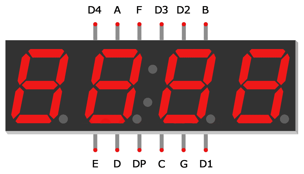
The LED display has four Cathodes. Each cathode is in common with one digit. D4, D3, D2, and D1 are all cathodes.

A, B, C, D, E, F, G, and DP all correspond to an individual section of the LED. The plan is to ground one cathode at a time. Then display the right digit by grounding the specific cathode pin. A shifting register (74HC595 IC) will be used to power the segment LEDs.
Required Hardware
STM Microcontroller
Shifting Register (74HC595 IC)
4-Digit 7-Segment Display
(4) 330-ohm Resistors
Configuring your Pins
You have some freedom when it comes to configuring your pins. The code will ask you to specify the configuration. It will then adjust itself accordingly. More information is in the Coding section of this page.
Shifting Register (74HC595 IC)
For more information about this register, please refer to the Shifting Register page of this wiki.
In your Pinout & Configuration tab, you'll need to go to the Connectivity section. There you will find SPI1. The mode will be Transmit Only Master. Under Parameter Settings, change Data Size to 8 bits. Also, note that First Bit is MSB First. What this means is that the most significant bit is going to be Q7 on the register.

This will automatically assign Pin PA5 as SPI1_SCK. That is the SHCP pin. Also, PA7 was assigned as SPI1_MOSI. That is the DS pin.
Next, assign PA6 and PA4 as GPIO_Output. These will be your STCP and MR pins.


Shifting Register to 4-Digit 7-Segment Display

4-Digit 7-Segment Display
All the Segment pins on the Display are connected to the Register. You'll need to configure 4 additional GPIO outputs. These will be connected to the Cathode pins. I used PA12, PA1, PA3, and PA2. Also, make sure to connect your resistors to protect your LEDs.

TIMER
The code also utilizes a timer for printing strings longer than 4 characters. The timer is directly tied to the System Clock. For the F303K8 board, the default System Clock is set to 8MHz. Next, the AHB Prescaler divides the System clock. For our purposes, the Prescaler will be set to 1. This leaves us with the HCLK frequency of 8 MHz, the same as the SYSCLK.

Next, go to your pinout & Configuration tab and select a timer. I selected Timer 16. Under Parameter, I set the Prescaler to 8000-1. This makes the Timer count Up in milliseconds. The minus 1 is because the prescaler starts at 0. SYSCLK/(AHB Prescaler * TIM16 Prescaler) = TIM16 Value.

Diagram

Code
Getting Started
After configuring the pins, generate the code and add seg_display.c to your Src file and add seg_display.h to your Inc file. You can retrieve these files from the Components folder in my repository. Next, add #include "seg_display.h" to your Private include section of your main.c.
/* Private includes ----------------------------------------------------------*/
/* USER CODE BEGIN Includes */

#include "seg_display.h"

/* USER CODE END Includes */

Next, go to your main function, and under User Code Begin two, write this:
/* USER CODE BEGIN 2 */
Register_HanldeTypeDef reg = registerCreate(hspi1, GPIOA, GPIO_PIN_6, GPIOA, GPIO_PIN_4);
char order[8] = {'b','a','g','c','p','d','e','f'};
Seg_Display_HandleTypeDef dis = createDisplay(GPIOA, GPIO_PIN_12,
GPIOA, GPIO_PIN_1,
GPIOA, GPIO_PIN_3,
GPIOA, GPIO_PIN_2,
&order[0],&htim16);
seg_display_init(&dis, ®);
char str[] = {"7-SEG DISPLAY."};
/* USER CODE END 2 */
Register
The first line of code is declaring your register.
Register_HanldeTypeDef registerCreate(SPI_HandleTypeDef hspi1,
				      GPIO_TypeDef * stcp_port, uint16_t stcp_pin,
				      GPIO_TypeDef * mr_port, uint16_t mr_pin)
/* SPI_HandleTypeDef structure that contains the configuration information for SPI module
 * stcp_port is the Storage register clock port
 * stcp_pin is the Storage register clock pin
 * mr_port is the master clear port
 * mr_pin is the master clear pin
 */
The first parameter is the SPI_HandleTypeDef. This is created automatically when you generated your code. The next parameter is the GPIO port and pin for STCP pin on the register. The last two parameters are the port and pin for the MR pin.
Segment Display
Creating an array of char is next. The first element of the array is the MSB connected to the Display. If you remember the Diagram, segment b of the display is connected to Q7 of the register. Following that is Seg a, g, c, etc. For Segment dp, go ahead and write that as char value 'p'.
Seg_Display_HandleTypeDef createDisplay(GPIO_TypeDef * d1_port, uint16_t d1_pin,
					GPIO_TypeDef * d2_port, uint16_t d2_pin,
					GPIO_TypeDef * d3_port, uint16_t d3_pin,
					GPIO_TypeDef * d4_port, uint16_t d4_pin,
					char * order, TIM_HandleTypeDef * timer)
The first 8 parameters are the GPIO ports & pins of the Display Cathodes. Next is the array of char that describes the order of the segments. Lastly, is the timer. That was also created automatically when you generated the code.
Printing
After that, you initialize the whole thing by passing the register and display. You then create your string.
seg_display_init(&dis, ®);
char str[] = {"7-SEG DISPLAY."};
In your infinite while loop, you're going to insert the printChar() function. It takes your string pointer and returns 1 if the entire string has been printed at least one time.
  /* Infinite loop */
  /* USER CODE BEGIN WHILE */
  while (1)
  {
    /* USER CODE END WHILE */
	  printChar(str);
    /* USER CODE BEGIN 3 */
  }
Functions
Now you have enough information to get started with your project. The following section will go into more depth on how the code works.
- createDisplay()
- registerCreate()
- seg_display_init()
These three public functions are self-explanatory. They inilize the display.
charMap()
seg_display_init() function uses this private charMap() function to convert the char values into data that can be sent to the register. I mapped all the ASCII values from 20h to 7Eh. Some characters couldn't be displayed in 7 segments, for example, 'w' or 'm', so for those ones, I left it blank. depending on how you connected the register to the display, you would have to map the character all over again. Mapping 95 characters is very time-consuming so I created the charMap() function that takes the connections and the original map and creates a new array. It does this through bit manipulation.

sendSPIdata()
This sends data to the register. You pass your Register_HanldeTypeDef and your array of uint8_t. This array contains the byte of data you want to send to that register.
void sendSPIdata(Register_HanldeTypeDef * reg, uint8_t data[])
/* Register_HandleTypeDef structure that contains the configuration information for the register module.
 * Data address to data buffer
 */
displayInt()
This function takes uint8_t array, size 4. This is your buffer. It's the four characters you want to display on your 4-Digit 7-Seg Display.
void displayInt(uint8_t * buffer)
/* Takes Array Size 4
 * Sends data to SPI to print onto 4-digit 7-Segment Display */
printChar()
This is where the magic happens. It takes your array of char. If the pointer to your string is new, then it initiates it. If it's not new, then it checks to see if the string is more than four characters. If it is, then it uses a timer to change the buffer every half a second. It uses the private function, shiftArray() to shift the buffer one element at a time. Once it's able to print the whole string, it returns a 1.
uint8_t printChar(char * str)
/* Takes Array of Char
 * Returns 1 if Entire Array was printed once */
shiftArray()
This is a private function used in printChar(). It takes the buffer and the new character. Then it shifts the whole array and inserts the new character in the last element of the array. It also converts the char character to an uint8_t.
static void shiftArray(uint8_t buf[], char new)