Analog Stage Theory of Operation - jkominek/piano-conversion GitHub Wiki
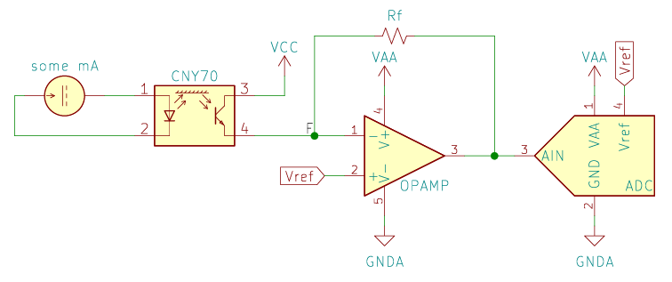
The short version for electrical engineers is that the CNY70 is a combination IR LED and IR-sensitive phototransistor. We feed the current from the phototransistor into a transimpedance amplifier, and the output goes into the ADC.
The rest of the document attempts to expand on how things work, but there's only so much I can cram into this, or care to cram into it. For additional background:
- find some basic electronics book here
- Operational amplifier @ Wikipedia
- Transimpedance amplifier @ Wikipedia
- TI has a number of app notes on everything relevant.
The CNY70
There are more details on the CNY70 itself on my other wiki page. We'll address briefly how it fits in.
In this design, the IR LED is powered by a constant-current supply, running at 20mA, in the form of the LED power board. We can simplify that down to a current loop for our purposes here.
The phototransistor acts/is a normal transistor, but instead of having the base brought out as a pin, the junction is exposed to light, so that photons can take the place of electrical current. As photons flow in, electronics are permitted to flow from the collector (CNY70 pin 3) to the emitter (CNY70 pin 4). We know from fig 5 of the CNY70 data sheet that more photons flowing in increases the current flowing through the transistor. (Why do we know that? The reflective target and everything else relevant is held steady as the LED forward current is changed. That affects how many photons are emitted; everything else constant, that means more hit the phototransistor.)
We can also see from fig 6 that for a fixed photon count, changing Vce (the voltage between collector and emitter) increased the current flow. Note, also, while we're looking at it, all of the annoying curvy nonlinearity of that relationship.
If Vce drops too low, relative to our incoming photons, our current through the phototransistor can drop, potentially to zero.
Transimpedance amplifier
The current flowing through the phototransistor ends up in the node labeled "F" in the schematic. By Kirchoff's Current Law, that current has to exit node F. The op amp inputs ("-", pin 1, and "+", pin 2) are ultra-high impedance (gigaohms, potentially, depending on the exact opamp chosen), so ~0 current is flowing into them. Thus, it must flow backwards through Rf. At that point, it can't flow into the ADC input, those are also very high impedance. So it flows into the op amp's "output", pin 3. From there the op amp will sink it to ground.
The op amp will adjust the voltage at the output pin in an attempt to keep the voltage between its two input pins at 0V. We know what Vref is, because we choose that, and nothing here can affect it. We "know" the current flowing out of the phototransistor (Ipt), and we know the resistor value (Rf). Output voltage = Vref - Rf * Ipt. As an example, if Vref is 2.0V, Rf is 2kOhm, and Ipt is 10uA, then the output voltage is 2.0V - 2000ohm * .00001A = 1.8V. More current will further lower the output voltage, as the op amp works to sink all of that current despite the voltage drop of the feedback resistor, Rf.
From this, we can see that Rf sets the amplification of the system. A large Rf gets us a larger change in the output for a given change in phototransistor current. As long as the amplification is low enough that the op amp can sink all of the necessary current, then the voltage at node F will remain equal to Vref. This is referred to as a virtual ground in electronics texts.
What is "low enough"? Our opamp can't output a voltage below the ground potential, 0V. And the high end is Vref. So a voltage of Vref is the most that can exist across Rf before our op amp will run into trouble sinking the current. V=RI again, Vref/Rf=Ipt_max. For specific values, 2.0V/2000ohm = 1mA. If Ipt exceeds 1mA, then the voltage at node F will begin to rise.
That has further ramifications. The phototransistor's current output depends on Vce. Vce is the difference between Vcc and node F. If node F goes up, then Vce drops. Per fig 6 of the CNY70 data sheet, if Vce drops, then Ipt will drop (for a given photon count). We don't want any of this to happen, as it will start causing a lot of odd behavior.
ADC behavior
The ADC measures AIN, and produces values proportional to (AIN-GND)/(Vref-GND), subject to all of the complexities of ADCs. See everything written about ADCs on the STM32H7 page. A 16 bit ADC will attempt to divide that range, from GND to Vref, up into 2^16 equally sized chunks. For a 2.0V Vref, that means every LSB will correspond to ~30.5uV.
Additional choices
Note that VAA is not the same as Vref. Many/most opamps are not rail-to-rail, or have difficulties when their output voltage approaches the rails. By keeping VAA > Vref, we avoid any issues with that.
Further, VAA also powers the analog circuitry of the STM32. We're running the digital logic at 3.3V, and the analog circuitry has to be powered by (basically) the same voltage, even if it comes from a different, cleaner, source. So we've got a clean analog 3.3V one way or the other. Might as well use it.
What about using 3.3V for Vref? Per the last section, Vce on the phototransistor is VAA-Vref. We want to keep Vce as high as is reasonable so that we don't sag into the particularly weird regions depicted in fig 5 of the data sheet. 2.0V for Vref strikes a balance between Vce, keeping the voltage of an ADC LSB reasonable, and holding Vce at Vcc-2.0V.
Ok, what is Vcc, then? The highest voltage available to us on the board is a 5V line coming in from the main board. While we try to keep that clean, it's being passed through from what is ultimately a switched-mode power supply. Not clean enough. What's the highest voltage we can get from that cleanly? Inexpensive low-dropout linear regulators are available with dropouts of 0.25V. We should given our input some headroom, and figure it is 5.0 +/- 0.25V. So 5 - 0.25 - 0.25 = 4.5. 4.5V LDOs are available, and should clean things up nicely. Vcc = 4.5V.
That leaves us with Vce = 4.5V - 2.0V = 2.5V. That's in a well-behaved region of fig 6 on the data sheet.