_SKU_DFR0416_Bluno_M0_Mainboard - jimaobian/DFRobotWikiCn GitHub Wiki
Bluno M0是当前唯一一款支持5V标准逻辑电平,采用ARM Cortex-M0内核的Arduino控制器。Bluno M0内置蓝牙芯片,支持蓝牙通信,无线编程等功能。 当我们使用传统的Arduino UNO来制作项目时,是否会发现UNO的管脚资源太少,处理性能又不够等问题?而Mega系列的主板又太贵,Arduino ZERO系列的主板又不兼容5V的供电设备。这些由于管脚,处理性能,电平差而产生的问题在遇到Bluno M0之后,都可以迎刃而解。 Bluno M0采用新唐高性能32位单片机作为处理核心,内置ARM Cortex M0架构,支持5V逻辑电平,拥有1个USB口以及2个硬件串口,拥有31个数字管脚(部分复用)以及6个模拟管脚。兼容Arduino Leonardo管脚封装,并且拥有更多的IO资源和更强大的运算速度。 此外DFRduino M0扩展了一个IIS接口,支持播放录制wav文件。配合高端IIS芯片,可以专业HIFI级的音频体验。
 |
|
| 注意: |
Bluno M0与官方的Arduino M0并不相同,使用了不同的芯片解决方案,需要独立安装IDE板卡,支持Windows,Linux,MAC全平台,默认1.6.0及以上版本,其他版本IDE可以按照FAQ中的说明自己做一些更改来使用。
Bluno M0基于Nuvoton NUC123ZD4AN0芯片开发,其设计目的在于找到一个高性价比的快速原型开发方案,软件的兼容性上还有些欠缺,建议上手前需要有一定的嵌入式开发经验。 |
- Arduino IDE 1.6+兼容
- 32-Bit 72MHz Cortex-M0处理核心
- 支持5V基准电压
- 支持标准IIS音频接口
- 支持USB及双物理硬件串口
- 兼容Leonardo管脚封装,比标准Leonardo多10个IO(其中2个可以配置为RX2 TX2)
- 支持蓝牙无线编程上传代码
- 支持Windows Linux Mac三平台
- 微控制器:Nuvoton NUC123ZD4AN0 (Cortex M0)
- 时钟速度:72MHz
- 工作电压:5V
- 推荐输入电压:7-12V
- 限制输入电压:6-20V
- 数字IO口:31
- 模拟输入:6
- 外部中断:2个(D2,D3)
- IIC/I2C:1个(D2,D3)
- SRAM:20K
- Flash:68K(其中Bootloader占用12K,用户可用代码区占用55K,EEPROM区占用1K)
- EEPROM 1K
- SPI:1个(D14,D15,D16)
- USB COM口:1个 (Serial)
- 蓝牙串口:Serial (USB COM口、蓝牙、D0&D1共用一个串口Serial)
- USB口:1个 (USBSerial)
- 物理串口:2个
- Serial D0(Rx1) 和 D1(Tx1)
- Serial2 D24(Rx2) 和 D25(Tx2)
- 尺寸:68.5 * 53.4(mm)
- 重量:30g
 dfr0416_with_tag_svg.png dfr0416_with_tag_svg.png
|
|
我们提供六路A0-A5模拟输入,其他接口兼容官方Leonardo 另外我们还提供了一些扩展接口 这张板子的IO映射表如下
| Duino管脚 | 对应的IC管脚 | 复用功能 | 备注 |
| D0 | PC4 | RXD1 | Serial-RX |
| D1 | PC5 | TXD1 | Serial-TX |
| D2 | PF2 | SDA | INT0 |
| D3 | PF3 | SCL | INT1 |
| D4 | PC0 | I2S LRCLK | 无 |
| D5 | PC3 | PWM0 | 无 |
| D6 | PA13 | PWM1 | 无 |
| D7 | PC2 | I2S DI | 无 |
| D8 | PC3 | I2S DO | 无 |
| D9 | PA14 | PWM2 | 无 |
| D10 | PA15 | PWM3 | 无 |
| D11 | PB8 | PWM4 | 软件模拟PWM |
| D12 | PC1 | I2S BCLK | 无 |
| D13 | PB14 | PWM5 | 软件模拟PWM |
| D14 | PA10 | SPI MISO | 无 |
| D15 | PA11 | SPI SCK | 无 |
| D16 | PC11 | SPI MOSI | 无 |
| D17 | PB6 | RX LED | 不建议用户使用 |
| D18 | PD0 | A0 | 无 |
| D19 | PD1 | A1 | 无 |
| D20 | PD2 | A2 | 无 |
| D21 | PD3 | A3 | 无 |
| D22 | PD4 | A4 | 无 |
| D23 | PD5 | A5 | 无 |
| D24 | PB4 | RXD2 | RX2 |
| D25 | PB5 | TXD2 | TX2 |
| D26 | PC10 | NULL | 无 |
| D27 | PC9 | NULL | 无 |
| D28 | PC13 | NULL | 无 |
| D29 | PC12 | NULL | 无 |
| D30 | PB9 | NULL | 无 |
| D31 | PB10 | NULL | 无 |
| D32 | PB7 | TX LED | 不建议用户使用 |
- 打开arduinoIDE,File->Preferences,在弹出的对话框中找到Additional Boards Manager URLs。在后面的文本框中填写:
https://raw.githubusercontent.com/DFRobot/DFRobotDuinoBoard/master/package_dfrobot_index.json ;
image:filepreferences.png|从这里进入 image:preferencesjson.png|在这里填入url
- 点击OK
- 选择Tools->Board->Boards Manager,arduinoIDE会更新我们的板子信息。
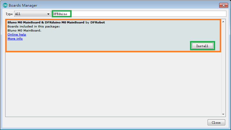
- 在搜索框中输入DFRduino,可以找到下面这个板子。点击Install
- 安装完成后显示为
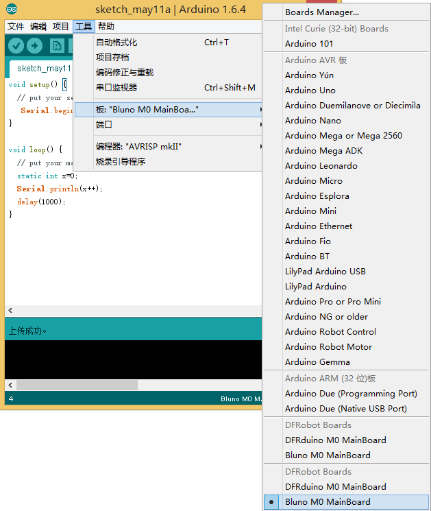
- 上面的boards manager安装完成后,IDE中即可找到对应的开发板Bluno M0 MainBoard
部分Win 10系统会自动安装驱动,请打开设备管理器,查看是否有**USB串行设备(COM X)**存在。

大部分系统,无法自动安装驱动,只能手动安装,步骤如下
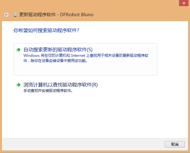
- 将标注COM的USB口查到电脑上,会弹出一个未识别的设备,显示如下
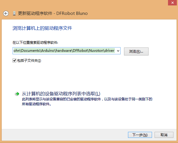
- 右击更新驱动程序,选择浏览计算机以查找驱动程序软件
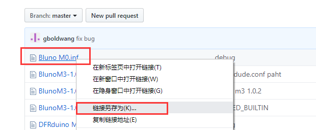
- 选择我们下载的SDK的driver子目录,如果找不到,从这里下载BlunoM0的串口驱动,(Bluno M0.inf文件,请使用“另存为”功能下载)。
- 点击下一步
- 选择始终安装驱动程序软件
- 安装完成后,效果如图所示
Bluno M0的蓝牙使用方式与Bluno系列保持了高度一致,这边就不多做赘述,详情参见:(SKU:DFR0267)Bluno蓝牙4.0控制器 兼容Arduino
- 物理串口D0&D1对应Serial ,物理串口2对应Serial2。对于物理串口,用户可以使用usb转串口工具查看打印。
实验代码
void setup() {  // put your setup code here, to run once:
    Serial.begin(115200);
    Serial2.begin(115200);
}
void loop() {   // put your main code here, to run repeatedly:
    Serial.println("I am Serial");
    Serial2.println("I am Serial 2");
    delay(1000);
}
实验结果 使用USB转串口接口板接收Serial2数据,在PC上打开软件观察。在标有COM丝印的USB口上和Serial2上都可以看到对应的打印输出。
实验代码
int pin;
void setup() {  // put your setup code here, to run once:
    for(pin=24;pin<32;pin++){
        pinMode(pin,OUTPUT);
    }
}
void loop() {   // put your main code here, to run repeatedly:
    for(pin=24;pin<32;pin++){
        digitalWrite(pin,HIGH);
    }
    delay(500);
    for(pin=24;pin<32;pin++){
        digitalWrite(pin,LOW);
    }
    delay(500);

}
实验结果 在数字口24-31上,有1HZ的电平跳变输出,接电压表可以看到电压跳变,接led可以看到闪烁。
|
#include <SPI.h>
#include <Wire.h>
#include <SD.h>
#include <WAV.h>

// set up variables using the SD utility library functions:
Sd2Card card;

const int chipSelect = 4;
void setup()
{
  // Open serial communications and wait for port to open:
  Serial.begin(115200);
  while (!Serial) {
    ; // wait for serial port to connect. Needed for Leonardo only
  }


  Serial.print("\nInitializing SD card...");

  // we'll use the initialization code from the utility libraries
  // since we're just testing if the card is working!
  if (!card.init(SPI_HALF_SPEED, chipSelect)) {
    Serial.println("initialization failed. Things to check:");
    Serial.println("* is a card inserted?");
    Serial.println("* is your wiring correct?");
    Serial.println("* did you change the chipSelect pin to match your shield or module?");
    return;
  } else {
    Serial.println("Wiring is correct and a card is present.");
  }
}

void loop()
{
   int ret=WAV_DECODING;
   wav.begin("test.wav");
   wav.play();
   while(ret == WAV_DECODING){
       ret = wav.decode();
   }
}
|}
Windows : Win7 32bit/64bit Win8 32bit/64bit Win10 32bit Linux : Ubuntu 12.04 32bit Mac : OSX 10.11
| 问: Linux下载时显示没有权限操作串口 |
- 答: 使用sudo usermod -a -G 当前用户名 dialout 将当前用户添加到dialout组,然后注销重新登陆即可。
| 问: 驱动文件找不到 |
- 答: 在sdk的driver目录下
| 更多问题及有趣的应用,可以 访问论坛 进行查阅或发帖! |

 warning_yellow.png
