_SKU_DFR0370_CAN BUS_Shield_V2 - jimaobian/DFRobotWikiCn GitHub Wiki
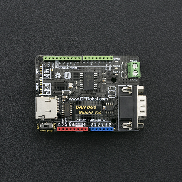
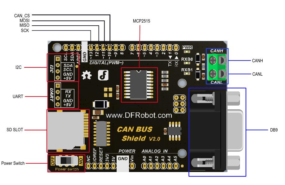
CAN-BUS Shield V2.0是专为Arduino控制器设计的扩展板,板载MCP2515总线控制芯片能够实现CAN总线上的数据控制,实现设备与设备之间的数据通信。扩展板兼容Arduino标准卡槽,可以完美适配于Arduino UNO,Leonardo等主控板。并且提供一个DB9和一个接线柱形式的接口,您可以根据需要自主选择接口。内嵌MicroSD卡槽,可直插MicroSD卡,存储数据。多种扩展接口使得用户在DIY过程中得到更大的便利。
- 支持标准帧、扩展帧收发,支持轮训和中断两种接收方式
- 提供uart、I2C、DB9及接线柱等多种接口
- 支持SD卡数据存储
- 支持Arduino主板供电以及DB9接口供电
- 芯片:MCP2515
- 供电:3.3~5VDC Arduino 主板供电/DB9接口供电
- 尺寸:76 mm * 54mm *19mm
- 重量:40g
 |
|
| 两种供电方式: |
Power Switch 处于“ON”端,电源由DB9接口的供电
Power Switch 处于“OFF”端,电源由Arduino主板供应
注意:
当DP9接口处的电压大于7V时可以为arduino主控板供电,开关选择”ON“;
如果arduino主板是usb供电,那么USB和DB9可以同时供电;如果arduino是DC-Vin电源供电,DB9就不能同时供电了,必须将开关置于”OFF“处 |
本节内容主要介绍如何用我们提供的函数库去DIY您的创意或者说您的产品。为了能够表述的容易理解,我们决定从最基础的知识开始介绍,然后结合一个例子进一步阐述。 1、can-bus节点(设备) 什么叫做can-bus节点呢? 首先我们要明确的一点就是can-bus是一个局域网控制协议。既然是局域网,那么该网络上一定有很多设备相连的。每个设备就是一个节点,而每个节点上有一个can-bus协议控制器(控制芯片)。
2、can-bus总线上的节点即可以作为接收器,又可以作为发射器,即一般来地,我们称can-bus的节点为收发器。
3、can-bus总线上没有地址的概念,所有can-bus的数据帧都是被id所区分,每个设备对应一个id。 假如A节点发送id为0x1123的标准数据帧,D节点也可以发送id为0x1123的标准数据帧。当然实际工程中很少这样,一般来说,不同的id对应不同的收发器,不同的收发器完成不同的功能;又或者相同的收发器发送不同的id,不同的id发送不同需求的数据。
4、can-bus节点依靠自身的硬件屏蔽功能,实现选择性的接受来自在初始化时指定id的数据帧。 可以通过调用**init_Mask(Masker_t Masker_num, INT8U ext, INT32U ulData)和init_Filter(Filter_t Filter_num, INT8U ext, INT32U Data)**配置选择性接受指定的id。参见Arduino库函数功能说明
5、can-bus总线上的任意一个节点发送的数据都可以被其他节点选择性的接受。该节点也可以选择性的接收其他节点发送的数据。
结合以上5点分析can-bus总线上的数据传输情况: 举例来说,假如在一个由五个节点的局域网中,节点名称分别是:A、B、C、D、E。其中B节点只可以接收id为0x06的标准数据帧,那么当节点A要向节点B发送数据“hello world”,那么可以调用我们的**sendMsgBuf(0x06, 0, 12, "hello world")**函数即可。此时这五个节点组成的局域网的总线(H线和L线)上,传输的就是包括“hello world”数据在内的标准数据帧,且该数据帧的id为0x06,那么节点B就可以接受到该数据帧了。
那么其他节点可以接受该数据帧吗?答案是可以的,只要你设定的id与发送时指定的id相符合,既可以接受数据,例如: 假设:
- 节点B的数据帧接收id:0x06
- 节点C的数据帧接收id:0x06和0x08
- 节点D的数据帧接收id:0x07
- 节点E的数据帧接收id:任意
那么:
- 当节点A发送id为0x06的标准数据帧时,那么可接收到的节点是B、C、E;
- 当节点A发送id为0x07的标准数据帧时,那么可接收到的节点是D、E;
- 当节点A发送id为0x08的标准数据帧时,那么可接收到的节点是C、E;
- 当节点A发送id为0x12的标准数据帧时,那么可接收到的节点是E;
MCPCAN(INT8U _CS) 函数功能: 构造函数,指定CAN-BUS Shield V1.0模块的CAN接口SPI的片选信号引脚。 参数说明:
- _CS:端口编号。
返回值:无。 使用方法:
MCPCAN CAN(4); // 用MCPCAN类实例化了一个CAN对象,可以用该对象调用该类的方法去控制can控制器。_CS 此处为4,表明arduino的数字管脚4作为spi的cs脚与can总线控制器相连接。
void init(void) 函数功能: 初始化spi模块,以及对MCP2515进行软件复位。 参数说明: 无 返回值:无。 使用方法:
该函数应该在一开始就调用,以初始化can总线控制器等。
INT8U begin(INT8U speedset) 函数功能: 初始化设置CAN的波特率,在init()后面使用。 参数说明:
- speedset:波特率,可以是:CAN_5KBPS、CAN_10KBPS、CAN_20KBPS、CAN_31K25BPS、CAN_33KBPS、CAN_40KBPS、CAN_50KBPS、CAN_80KBPS、CAN_83K3BPS、CAN_95KBPS、CAN_100KBPS、CAN_125KBPS、CAN_200KBPS、CAN_250KBPS、CAN_500KBPS、CAN_1000KBPS。
返回值:如果初始化成功返回CAN_OK,如果初始化失败返回CAN_FAILINIT。 使用方法:
begin(CAN_500KBPS);
INT8U sendMsgBuf(INT32U id, INT8U ext, INT8U len, INT8U *buf) 函数功能:发送一帧数据。 参数说明:
- id:该数据帧的id编号。
- ext:如果ext = 0,则表示该数据帧是标准的数据帧,如果ext = 1,则表示该数据帧是扩展数据帧。
- len:数据长度,len < 8。
- buf:将要发送的数据缓存指针。
返回值:如果发送成功,则返回CAN_OK,如果发送超时,则返回CAN_SENDMSGTIMEOUT。如果获取下一个空闲buffer失败,则返回CAN_GETTXBFTIMEOUT。 使用方法:
unsigned char data[8] = {'D', 'F', 'R', 'O', 'B', 'O', 'T', '!'};
sendMsgBuf(0x06, 0, sizeof(data), data);
INT8U MCPCAN::setMsg(INT32U id, INT8U ext, INT8U len, INT8U rtr, INT8U *pData) 函数功能:发送远程发送请求报文。 参数说明:
- id:该数据帧的id编号。
- ext:如果ext = 0,则表示该数据帧是标准帧,如果ext = 1,则表示该数据帧是扩展帧。
- len:数据长度,len < 8。
- rtr: 如果rtr = 1,则表示此帧数据为远程发送请求帧;如果rtr = 0,则表示此帧数据为数据帧。
- buf:将要发送的数据缓存指针。
返回值:如果发送成功,则返回CAN_OK,如果发送超时,则返回CAN_SENDMSGTIMEOUT。如果获取下一个空闲buffer失败,则返回CAN_GETTXBFTIMEOUT。 使用方法:
unsigned char data[8] = {'D', 'F', 'R', 'O', 'B', 'O', 'T', '!'};
setMsg(0x06, 0, sizeof(data), 0, data);
INT8U isRemoteRequest(void) 函数功能:判断是否是远程遥控帧。 参考说明 无 返回值:如果返回1,表示该数据帧是远程遥控帧,如果返回0,则表示不是远程遥控帧。
INT8U init_Mask(Masker_t Masker_num, INT8U ext, INT32U Data) 函数功能:初始化屏蔽寄存器。 参数说明:
-
Masker_num: Masker_num 可以为:MCP_RXM0、MCP_RXM1。若Masker_num = MCP_RXM0 ,表示初始化屏蔽寄存器0(屏蔽寄存器0是接收buffer0的);若Masker_num = MCP_RXM1,表示初始化屏蔽寄存器1(屏蔽寄存器1是接收buffer1的)
-
ext: 如果ext = 0,表示对标准数据帧进行屏蔽寄存器设置,如果ext=1,表示对扩展帧进行配置。
-
Data: 该值写入到屏蔽寄存器中,用于配置哪些为将被屏蔽。
返回值:如果Masker_num即不是MCP_RXM0也不是MCP_RXM1或者初始化屏蔽寄存器失败,则返回MCP_FAIL;如果初始化屏蔽寄存器成功则返回MCP_OK; 使用方法:
init_Mask(MCP_RXM0, 0, 0x3ff); //在init()函数之后使用,begin()之前。期望对标准帧的0~9位进行过滤共10位,因为0x3ff的二进制形式是11 1111 1111,这里刚好10位。
INT8U checkReceive(void) 函数功能:检测是否接收到有效的数据帧。 参数说明: 无 返回值:如果接收到有效的数据帧,则返回CAN_MSGAVAIL;如果没有接收到有效的数据帧,则返回CAN_NOMSG; 使用方法:
在can总线控制器工作起来后,可以轮训调用该函数来检测是否接收到有效的数据帧,请参见下面样例。
INT8U init_Filter(Filter_t Filter_num, INT8U ext, INT32U Data) 函数功能:初始化报文验收滤波寄存器。 参数说明:
-
Filter_num: 报文验证滤波器编号。Filter_num取值可以为:MCP_RXF0、 MCP_RXF1、 MCP_RXF2、 MCP_RXF3、 MCP_RXF4、 MCP_RXF5。
-
ext:如果ext = 0,则表示该报文验收滤波器只验收标准数据帧报文,如果ext = 1,则表示该报文验收滤波器只验收扩展数据帧报文。
-
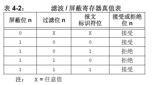
Data:将被过滤的报文id。只有能被过滤的id的数据帧才能被can控制器接收。因此一个即将到来的数据帧能否被接收到,取决与init_Mask()函数中对MCP_RXM0,MCP_RXM1寄存器所写的值、init_Filter()函数对MCP_RXF0等寄存器所写的值以及即将到来的报文标识符ID。这三者的值按位查看表4-2的真值表。如果每一位的真值结果全为接收,那么该报文将被can控制器接收,否则将被其丢弃。比如说init_Mask(MCP_RXM0, 0, 0x7ff)函数把MCP_RXM0寄存器配置为0x7ff,表示将要对标准帧ID的11个位进行屏蔽功能。且此时init_Filter (MCP_RXF0, 0, 0x20)函数把MCP_RXF0寄存器配置为0x20,将0x20(000 0010 0000对应表4.2中的过滤位)与0x7ff(111 1111 1111 对应表4.2中的屏蔽位)中每一位按照表4.2中的真值表来决定是否接受,如果每一位的对应的真值都是接受的话,那么该ID就可以被接收,如果这11位中有一个真值是拒绝的话就表示该ID所代表的数据帧会被丢弃。该例中根据真值情况,控制器能接收id为0x20的标准报文,而不能接收其他id的报文。当然根据真值表,当用init_Mask(MCP_RXM0, 0, 0x7DF)把MCP_RXM0改为了0x7DF后,MCP_RXF0仍为0x20,此时根据真值表,can控制器可以接受即将到来的0x20数据帧。
init_Mask(MCP_RXM0, 0, 0x7ff);
init_Filter(MCP_RXF0, 0, 0x04);//在init()函数之后,begin()之前使用,且和init_Mask()共同起作用。设置can控制器对标准帧id 0x04进行接收。
INT8U readMsgBuf(INT8U *len, INT8U *buf) 函数功能:从MCP2515接收buffer中读取数据。 参数说明:
- len:保存接收到的数据长度。
- buf:保存接收到的数据。
返回值:如果返回CAN_OK,则表示读取数据成功;反之返回CAN_NOMSG。 使用方法:
在can总线工作起来后,如果有数据帧到来调用该函数可以把该数据帧读出来,参见后续章节样例。
INT8U readMsgBufID(INT32U *ID, INT8U *len, INT8U *buf) 函数功能:从MCP2515接收buffer中读取数据,并读取此帧数据的id。 参数说明:
- ID : 保存此帧数据的id。
- len:保存接收到的数据长度。
- buf:保存接收到的数据。
返回值:如果返回CAN_OK,则表示读取数据成功;反之返回CAN_NOMSG。 使用方式:
用法同readMsgBuf()函数类似只是多了一个ID用于返回该帧数据的ID号。
INT8U checkError(void) 函数功能:检测MCP2515是否发送控制错误。 参数说明: 无。 返回值:如果发送了控制错误,则返回CAN_CTRLERROR;反之返回CAN_OK。
INT32U getCanId(void) 函数说明:获取当前帧的id。 参数说明: 无。 返回值:帧id。
当接收到数据后,调用此函数用于得到接收到的数据帧的ID,参见后续章节样例。
INT8U isExtendedFrame(void) 函数说明:判断当前帧是否为扩展帧。 参数说明: 无 返回值:如果返回1,则表示当前帧为扩展帧;如果返回0,则表示当前帧是标准帧。
在接收中断处理函数中调用,以判断数据帧是标准数据帧还是扩展帧。
-
硬件
- UNO x3
- CAN-BUS Shield V2 x3
- 杜邦线 x4
-
软件
- Arduino IDE 版本1.6.6 点击下载Arduino IDE
- CAN-BUS Shield库文件。如何安装库?
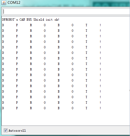
本实验测试基本的CAN收发功能,其中接收采用轮询方式,可以接受任意id的标准数据帧或扩展帧。发射节点每隔100ms发送一帧id为0x06的标准数据帧。
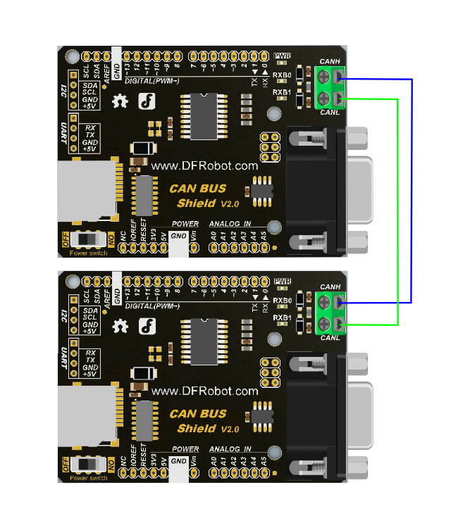
CAN-BUS Shield V2.0模块组网时,模块间连线为:CANH与CANH相连接,CANL与CANL相连接,如下图:
|
/******************************************************************************
* demo: CAN-BUS Shield, receive data with check mode
* send data coming to fast, such as less than 10ms, you can use this way
* Jansion, 2015.5.27
******************************************************************************/
#include <SPI.h>
#include "df_can.h"
const int SPI_CS_PIN = 10;
MCPCAN CAN(SPI_CS_PIN);                                    // Set CS pin
void setup()
{
      Serial.begin(115200);
      int count = 50;                                     // the max numbers of initializint the CAN-BUS, if initialize failed first!.
      do {
          CAN.init();   //must initialize the Can interface here!
          if(CAN_OK == CAN.begin(CAN_500KBPS))                   // init can bus : baudrate = 500k
          {
              Serial.println("DFROBOT's CAN BUS Shield init ok!");
              break;
          }
          else
          {
              Serial.println("DFROBOT's CAN BUS Shield init fail");
              Serial.println("Please Init CAN BUS Shield again");

              delay(100);
              if (count <= 1)
                  Serial.println("Please give up trying!, trying is useless!");
          }

      }while(count--);

}
void loop()
{
      unsigned char len = 0;
      unsigned char buf[8];

      if(CAN_MSGAVAIL == CAN.checkReceive())            // check if data coming
      {
          CAN.readMsgBuf(&len, buf);    // read data,  len: data length, buf: data buf

          for(int i = 0; i<len; i++)    // print the data
          {
              Serial.write(buf[i]);
              Serial.print("\t");
          }
          Serial.println();
      }
}
|}
|
  // demo: CAN-BUS Shield, send data
  #include <df_can.h>
  #include <SPI.h>

  const int SPI_CS_PIN = 10;

  MCPCAN CAN(SPI_CS_PIN);                                    // Set CS pin

  void setup()
  {
      Serial.begin(115200);
      int count = 50;                                     // the max numbers of initializint the CAN-BUS, if initialize failed first!.
      do {
          CAN.init();   //must initialize the Can interface here!
          if(CAN_OK == CAN.begin(CAN_500KBPS))                   // init can bus : baudrate = 500k
          {
              Serial.println("DFROBOT's CAN BUS Shield init ok!");
              break;
          }
          else
          {
              Serial.println("DFROBOT's CAN BUS Shield init fail");
              Serial.println("Please Init CAN BUS Shield again");

              delay(100);
              if (count <= 1)
                  Serial.println("Please give up trying!, trying is useless!");
          }

      }while(count--);

}

unsigned char data[8] = {'D', 'F', 'R', 'O', 'B', 'O', 'T', '!'};
void loop()
  {
      // send data:  id = 0x06, standrad flame, data len = 8, data: data buf
      CAN.sendMsgBuf(0x06, 0, 8, data);
      delay(100);                       // send data per 100ms
  }
|}
接收方:串口输出:
本实验测试基本收发功能,接收采用中断方式。
|
/***********************************************************
  *demo: CAN-BUS Shield, receive data with interrupt mode
  * when in interrupt mode, the data coming can't be too fast, must >20ms, or else you can use check mode
  * Jansion, 2015-5-27
***********************************************************/
  #include <SPI.h>
  #include "df_can.h"

  const int SPI_CS_PIN = 10;
  MCPCAN CAN(SPI_CS_PIN);                                    // Set CS pin


  unsigned char flagRecv = 0;
  unsigned char len = 0;
  unsigned char buf[8];
  char str[20];

  void setup()
  {
      Serial.begin(115200);
      int count = 50;                                     // the max numbers of initializint the CAN-BUS, if initialize failed first!.
      do {
          CAN.init();   //must initialize the Can interface here!
          if(CAN_OK == CAN.begin(CAN_500KBPS))                   // init can bus : baudrate = 500k
          {
              Serial.println("DFROBOT's CAN BUS Shield init ok!");
              break;
          }
          else
          {
              Serial.println("DFROBOT's CAN BUS Shield init fail");
              Serial.println("Please Init CAN BUS Shield again");

              delay(100);
              if (count <= 1)
                  Serial.println("Please give up trying!, trying is useless!");
          }

      }while(count--);


      attachInterrupt(0, MCP2515_ISR, FALLING); // start interrupt
  }

  void MCP2515_ISR()
  {
      flagRecv = 1;
  }

  void loop()
  {
      if(flagRecv)
      {                                   // check if get data

          flagRecv = 0;                   // clear flag

          // iterate over all pending messages
          // If either the bus is saturated or the MCU is busy,
          // both RX buffers may be in use and after having read a single
          // message, MCU does  clear the corresponding IRQ conditon.
          while (CAN_MSGAVAIL == CAN.checkReceive())
          {
              // read data,  len: data length, buf: data buf
              CAN.readMsgBuf(&len, buf);

              // print the data
              for(int i = 0; i<len; i++)
              {
                  Serial.write(buf[i]);Serial.print("\t");
              }
              Serial.println();
          }
      }
  }
|}
|
  // demo: CAN-BUS Shield, send data
  #include <df_can.h>
  #include <SPI.h>

  const int SPI_CS_PIN = 10;

  MCPCAN CAN(SPI_CS_PIN);                                    // Set CS pin

  void setup()
  {
      Serial.begin(115200);
      int count = 50;                                     // the max numbers of initializint the CAN-BUS, if initialize failed first!.
      do {
          CAN.init();   //must initialize the Can interface here!
          if(CAN_OK == CAN.begin(CAN_500KBPS))                   // init can bus : baudrate = 500k
          {
              Serial.println("DFROBOT's CAN BUS Shield init ok!");
              break;
          }
          else
          {
              Serial.println("DFROBOT's CAN BUS Shield init fail");
              Serial.println("Please Init CAN BUS Shield again");

              delay(100);
              if (count <= 1)
                  Serial.println("Please give up trying!, trying is useless!");
          }

      }while(count--);

  }

  unsigned char data[8] = {'D', 'F', 'R', 'O', 'B', 'O', 'T', '!'};
  void loop()
  {
      // send data:  id = 0x06, standrad flame, data len = 8, data: data buf
      CAN.sendMsgBuf(0x06, 0, 8, data);
      delay(100);                       // send data per 100ms
  }
|}
接收方:串口中输出:
本实验测试只接受初始化CAN模块时指定id的数据帧,接收采用中断方式。
|
/**************************************************************************************************************
   *demo: CAN-BUS Shield, receive data with interrupt mode, and set mask and filter
   * when in interrupt mode, the data coming can't be too fast, must >20ms, or else you can use check mode
   * Jansion, 2015-5-27
 ****************************************************************************************************************/
  #include <SPI.h>
  #include "df_can.h"
  const int SPI_CS_PIN = 10;
  MCPCAN CAN(SPI_CS_PIN);                                    // Set CS pin
  unsigned char flagRecv = 0;
  unsigned char len = 0;
  unsigned char buf[8];
  char str[20];
  void setup()
  {
      Serial.begin(115200);
      int count = 50;                                     // the max numbers of initializint the CAN-BUS, if initialize failed first!.

      do {
          CAN.init();   //must initialize the Can interface here!
          CAN.init_Mask(MCP_RXM0, 0, 0x3ff);                         // there are 2 mask in mcp2515, you need to set both of them
          CAN.init_Mask(MCP_RXM1, 0, 0x3ff);
          /*
           * set filter, we can receive id from 0x04 ~ 0x09 except for 0x06
           * // there are 6 filter in mcp2515,so it can filter six id,i.e.0x04~0x09.
           */
          CAN.init_Filter(MCP_RXF0, 0, 0x04);                         // filter 0 for id = 0x04
          CAN.init_Filter(MCP_RXF1, 0, 0x05);                         // filter 1 for id = 0x05
          // CAN.init_Filter(MCP_RXF2, 0, 0x06);                         // filter 2 for id = 0x06
          CAN.init_Filter(MCP_RXF3, 0, 0x07);                         // filter 3 for id = 0x07
          CAN.init_Filter(MCP_RXF4, 0, 0x08);                         // filter 4 for id = 0x08
          CAN.init_Filter(MCP_RXF5, 0, 0x09);                         // filter 5 for id = 0x09
          if(CAN_OK == CAN.begin(CAN_500KBPS))                   // init can bus : baudrate = 500k
          {
              Serial.println("DFROBOT's CAN BUS Shield init ok!");
              break;
          }
          else
          {
              Serial.println("DFROBOT's CAN BUS Shield init fail");
              Serial.println("Please Init CAN BUS Shield again");

              delay(100);
              if (count <= 1)
                  Serial.println("Please give up trying!, trying is useless!");
          }

      }while(count--);

      attachInterrupt(0, MCP2515_ISR, FALLING); // start interrupt


      /*
       * set mask, set both the mask to 0x3ff
       */

  }

  void MCP2515_ISR()
  {
      flagRecv = 1;
  }

  void loop()
  {
      if(flagRecv)                   // check if get data
      {

          flagRecv = 0;                // clear flag
          CAN.readMsgBuf(&len, buf);    // read data,  len: data length, buf: data buf

          Serial.println("\r\n------------------------------------------------------------------");
          Serial.print("Get Data From id: ");
          Serial.println(CAN.getCanId());
          for(int i = 0; i<len; i++)    // print the data
          {
              Serial.print("0x");
              Serial.print(buf[i], HEX);
              Serial.print("\t");
          }
          Serial.println();

      }
  }
|}
|
  /***************************************************************
  * demo: set_mask_filter_send
  * this demo will show you how to use mask and filter
  * Jansion, 2015-5-27
  *****************************************************************/
  #include <df_can.h>
  #include <SPI.h>
  const int SPI_CS_PIN = 10;
  MCPCAN CAN(SPI_CS_PIN);                                   // Set CS pin
  void setup()
  {
      Serial.begin(115200);
      int count = 50;                                     // the max numbers of initializint the CAN-BUS, if initialize failed first!.
      do {
          CAN.init();   //must initialize the Can interface here!
          if(CAN_OK == CAN.begin(CAN_500KBPS))                   // init can bus : baudrate = 500k
          {
              Serial.println("DFROBOT's CAN BUS Shield init ok!");
              break;
          }
          else
          {
              Serial.println("DFROBOT's CAN BUS Shield init fail");
              Serial.println("Please Init CAN BUS Shield again");

              delay(100);
              if (count <= 1)
                  Serial.println("Please give up trying!, trying is useless!");
          }

      }while(count--);
  }

  unsigned char data[8] = {'D', 'F', 'R', 'O', 'B', 'O', 'T', '!'};

  void loop()
  {
      for(int id=0; id<10; id++)
      {
          memset(data, id, sizeof(data));                 // set id to send data buff, id is arranged form 0x00 to 0x09.
          CAN.sendMsgBuf(id, 0, sizeof(data), data);
          delay(100);
      }
  }
|}
接收方:串口输出:
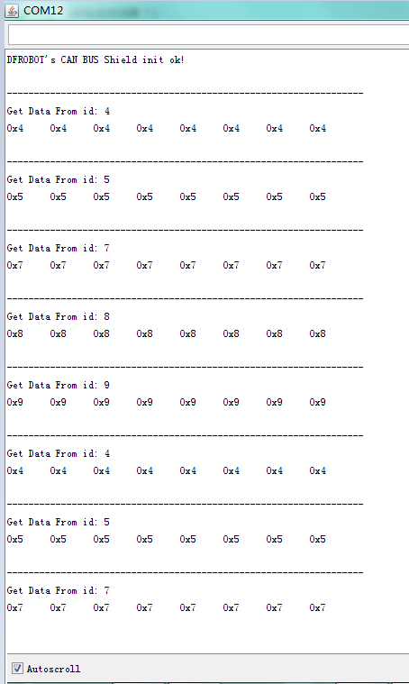
本实验测试三个模块组网,数据的收发情况。三个模块中每个模块既可以作为接收者,也可以作为发送者。本实验中3个节点设备,分别为称为node 1,node 2, node 3。其中node 1只作为接收节点,可以接收id为0x04,0x05,0x07,0x08,0x09的数据帧;node 2只接收id 为0x09的数据帧和发送id为0x08且数据为”node 2“的数据帧;node 3只接收id 为0x08的数据帧和发送id为0x09且数据为”node 3“的数据帧;
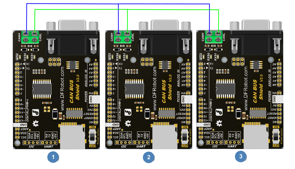
3个CAN-BUS Shield V2.0模块组网时,模块间连线为:CANH与CANH相连接,CANL与CANL相连接,如下图:
|
/**************************************************************************************************************
  *demo: CAN-BUS Shield, receive data with interrupt mode, and set mask and filter
  * when in interrupt mode, the data coming can't be too fast, must >20ms, or else you can use check mode
  * Jansion, 2015-5-27
****************************************************************************************************************/
  #include <SPI.h>
  #include "df_can.h"

  const int SPI_CS_PIN = 10;
  MCPCAN CAN(SPI_CS_PIN);                                    // Set CS pin
  unsigned char flagRecv = 0;
  unsigned char len = 0;
  unsigned char buf[8];
  char str[20];
  void setup()
  {
      Serial.begin(115200);
      int count = 50;                                     // the max numbers of initializint the CAN-BUS, if initialize failed first!.

      do {
          CAN.init();   //must initialize the Can interface here!
          CAN.init_Mask(MCP_RXM0, 0, 0x3ff);                         // there are 2 mask in mcp2515, you need to set both of them
          CAN.init_Mask(MCP_RXM1, 0, 0x3ff);
          /*
           * set filter, we can receive id from 0x04 ~ 0x09 except for 0x06
           * // there are 6 filter in mcp2515,so it can filter six id,i.e.0x04~0x09.
           */
          CAN.init_Filter(MCP_RXF0, 0, 0x04);                         // filter 0 for id = 0x04
          CAN.init_Filter(MCP_RXF1, 0, 0x05);                         // filter 1 for id = 0x05
          // CAN.init_Filter(MCP_RXF2, 0, 0x06);                         // filter 2 for id = 0x06
          CAN.init_Filter(MCP_RXF3, 0, 0x07);                         // filter 3 for id = 0x07
          CAN.init_Filter(MCP_RXF4, 0, 0x08);                         // filter 4 for id = 0x08
          CAN.init_Filter(MCP_RXF5, 0, 0x09);                         // filter 5 for id = 0x09
          if(CAN_OK == CAN.begin(CAN_500KBPS))                   // init can bus : baudrate = 500k
          {
              Serial.println("DFROBOT's CAN BUS Shield init ok!");
              break;
          }
          else
          {
              Serial.println("DFROBOT's CAN BUS Shield init fail");
              Serial.println("Please Init CAN BUS Shield again");

              delay(100);
              if (count <= 1)
                  Serial.println("Please give up trying!, trying is useless!");
          }

      }while(count--);

      attachInterrupt(0, MCP2515_ISR, FALLING); // start interrupt


      /*
       * set mask, set both the mask to 0x3ff
       */

  }

  void MCP2515_ISR()
  {
      flagRecv = 1;
  }

  void loop()
  {
      if(flagRecv)                   // check if get data
      {

          flagRecv = 0;                // clear flag
          CAN.readMsgBuf(&len, buf);    // read data,  len: data length, buf: data buf

          Serial.println("\r\n------------------------------------------------------------------");
          Serial.print("Get Data From id: ");
          Serial.println(CAN.getCanId());
          for(int i = 0; i<len; i++)    // print the data
          {
             Serial.write(buf[i]);
             Serial.print("\t");
          }
          Serial.println();

      }
  }
|}
|
   #include <SPI.h>
   #include "df_can.h"

   const int SPI_CS_PIN = 10;
   MCPCAN CAN(SPI_CS_PIN);                                    // Set CS pin
   unsigned char flagRecv = 0;
   unsigned char len = 0;
   unsigned char buf[8];
   char str[20];
   void setup()
   {
     Serial.begin(115200);
     int count = 50;                                     // the max numbers of initializint the CAN-BUS, if initialize failed first!.

     do {
         CAN.init();   //must initialize the Can interface here!
         CAN.init_Mask(MCP_RXM0, 0, 0x3ff);                         // there are 2 mask in mcp2515, you need to set both of them
         CAN.init_Mask(MCP_RXM1, 0, 0x3ff);
         /*
          * set filter, we can receive id from 0x04 ~ 0x09 except for 0x06
          * // there are 6 filter in mcp2515,so it can filter six id,i.e.0x04~0x09.
          */
         CAN.init_Filter(MCP_RXF5, 0, 0x09);                         // filter 5 for id = 0x09
         if(CAN_OK == CAN.begin(CAN_500KBPS))                   // init can bus : baudrate = 500k
         {
             Serial.println("DFROBOT's CAN BUS Shield init ok!");
             break;
         }
         else
         {
             Serial.println("DFROBOT's CAN BUS Shield init fail");
             Serial.println("Please Init CAN BUS Shield again");

             delay(100);
             if (count <= 1)
                 Serial.println("Please give up trying!, trying is useless!");
         }

     }while(count--);

     attachInterrupt(0, MCP2515_ISR, FALLING); // start interrupt


     /*
      * set mask, set both the mask to 0x3ff
      */

   }

   void MCP2515_ISR()
   {
     flagRecv = 1;
   }


   unsigned char data[] = "node 2";
   void loop()
   {
     if(flagRecv)                   // check if get data
     {
         flagRecv = 0;                // clear flag
         CAN.readMsgBuf(&len, buf);    // read data,  len: data length, buf: data buf

         Serial.println("\r\n------------------------------------------------------------------");
         Serial.print("Get Data From id: ");
         Serial.println(CAN.getCanId());
         for(int i = 0; i<len; i++)    // print the data
         {

             Serial.write(buf[i]);
             Serial.print("\t");
         }
         Serial.println();
     }

     // send data:  id = 0x08, standrad flame, data len = 8, data: data buf
     CAN.sendMsgBuf(0x08, 0, sizeof(data), data);
     delay(1000);                       // send data per 100ms

   }
|}
|
   #include <SPI.h>
   #include "df_can.h"

   const int SPI_CS_PIN = 10;
   MCPCAN CAN(SPI_CS_PIN);                                    // Set CS pin
   unsigned char flagRecv = 0;
   unsigned char len = 0;
   unsigned char buf[8];
   char str[20];
   void setup()
   {
     Serial.begin(115200);
     int count = 50;                                     // the max numbers of initializint the CAN-BUS, if initialize failed first!.

     do {
         CAN.init();   //must initialize the Can interface here!
         CAN.init_Mask(MCP_RXM0, 0, 0x3ff);                         // there are 2 mask in mcp2515, you need to set both of them
         CAN.init_Mask(MCP_RXM1, 0, 0x3ff);
         /*
          * set filter, we can receive id from 0x04 ~ 0x09 except for 0x06
          * // there are 6 filter in mcp2515,so it can filter six id,i.e.0x04~0x09.
          */
         CAN.init_Filter(MCP_RXF5, 0, 0x08);                         // filter 5 for id = 0x09
         if(CAN_OK == CAN.begin(CAN_500KBPS))                   // init can bus : baudrate = 500k
         {
             Serial.println("DFROBOT's CAN BUS Shield init ok!");
             break;
         }
         else
         {
             Serial.println("DFROBOT's CAN BUS Shield init fail");
             Serial.println("Please Init CAN BUS Shield again");

             delay(100);
             if (count <= 1)
                 Serial.println("Please give up trying!, trying is useless!");
         }

     }while(count--);

     attachInterrupt(0, MCP2515_ISR, FALLING); // start interrupt


     /*
      * set mask, set both the mask to 0x3ff
      */

   }

   void MCP2515_ISR()
   {
     flagRecv = 1;
   }


   unsigned char data[] = "node 3";
   void loop()
   {
     if(flagRecv)                   // check if get data
     {
         flagRecv = 0;                // clear flag
         CAN.readMsgBuf(&len, buf);    // read data,  len: data length, buf: data buf

         Serial.println("\r\n------------------------------------------------------------------");
         Serial.print("Get Data From id: ");
         Serial.println(CAN.getCanId());
         for(int i = 0; i<len; i++)    // print the data
         {

             Serial.write(buf[i]);
             Serial.print("\t");
         }
         Serial.println();
     }

     // send data:  id = 0x08, standrad flame, data len = 8, data: data buf
     CAN.sendMsgBuf(0x09, 0, sizeof(data), data);
     delay(1000);                       // send data per 100ms

   }
|}
CAN接收方串口不断输出下图信息:

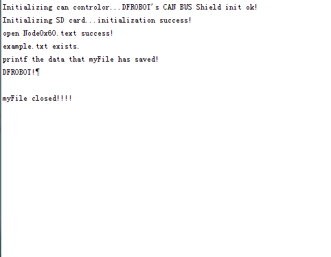
本实验的目的是:接收节点接收十条发送节点传来的数据,然后将其出入到CAN-BUS Shield sd卡中。最后将其读出并通过串口打印出来。
把SD卡插入到can-bus扩展板上,模块间连线为:CANH与CANH相连接,CANL与CANL相连接,如下图:
|
 // demo: CAN-BUS Shield, send data
  #include <df_can.h>
  #include <SPI.h>

  const int SPI_CS_PIN = 10;

  MCPCAN CAN(SPI_CS_PIN);                                    // Set CS pin

  void setup()
  {
      Serial.begin(115200);
      int count = 50;                                     // the max numbers of initializint the CAN-BUS, if initialize failed first!.
      do {
          CAN.init();   //must initialize the Can interface here!
          if(CAN_OK == CAN.begin(CAN_500KBPS))                   // init can bus : baudrate = 500k
          {
              Serial.println("DFROBOT's CAN BUS Shield init ok!");
              break;
          }
          else
          {
              Serial.println("DFROBOT's CAN BUS Shield init fail");
              Serial.println("Please Init CAN BUS Shield again");

              delay(100);
              if (count <= 1)
                  Serial.println("Please give up trying!, trying is useless!");
          }

      }while(count--);

  }

  unsigned char data[8] = {'D', 'F', 'R', 'O', 'B', 'O', 'T', '!'};
  void loop()
  {
      // send data:  id = 0x60, standrad flame, data len = 8, data: data buf
      CAN.sendMsgBuf(0x60, 0, 8, data);
      delay(1000);                       // send data per 100ms
  }
|
 /**************************************************************************************************************
 *demo: CAN-BUS Shield, receive data with interrupt mode, and set mask and filter
 * when in interrupt mode, the data coming can't be too fast, must >20ms, or else you can use check mode
 * Jansion, 2015-5-27
 ****************************************************************************************************************/
#include <SPI.h>
#include "df_can.h"
#include <SD.h>

const int SPI_CS_PIN = 10;
MCPCAN CAN(SPI_CS_PIN);                                    // Set CS pin
unsigned char flagRecv = 0;
unsigned char len = 0;
unsigned char buf[8];
char str[20];
char  sd_cspin = 4; //pin 4 as spi_cs pin
File myFile;

void setup()
{
    Serial.begin(115200);
    int count = 50;                                     // the max numbers of initializint the CAN-BUS, if initialize failed first!.
    Serial.print("Initializing can controlor...");
    do {
        CAN.init();   //must initialize the Can interface here!
        CAN.init_Mask(MCP_RXM0, 0, 0x3ff);                         // there are 2 mask in mcp2515, you need to set both of them
        CAN.init_Mask(MCP_RXM1, 0, 0x3ff);
        /*
         * set filter, we can receive id from 0x04, 0x05, 0x60, 0x07, 0x08, 0x09
         *
         */
        CAN.init_Filter(MCP_RXF0, 0, 0x04);                         // filter 0 for id = 0x04
        CAN.init_Filter(MCP_RXF1, 0, 0x05);                         // filter 1 for id = 0x05
        CAN.init_Filter(MCP_RXF2, 0, 0x60);                         // filter 2 for id = 0x60
        CAN.init_Filter(MCP_RXF3, 0, 0x07);                         // filter 3 for id = 0x07
        CAN.init_Filter(MCP_RXF4, 0, 0x08);                         // filter 4 for id = 0x08
        CAN.init_Filter(MCP_RXF5, 0, 0x09);                         // filter 5 for id = 0x09
        if(CAN_OK == CAN.begin(CAN_500KBPS))                   // init can bus : baudrate = 500k
        {
            Serial.println("DFROBOT's CAN BUS Shield init ok!");
            break;
        }
        else
        {
            Serial.println("DFROBOT's CAN BUS Shield init fail");
            Serial.println("Please Init CAN BUS Shield again");

            delay(100);
            if (count <= 1)
                Serial.println("Please give up trying!, trying is useless!");
        }

    }while(count--);

    attachInterrupt(0, MCP2515_ISR, FALLING); // start interrupt

    Serial.print("Initializing SD card...");

    if (!SD.begin(sd_cspin)) {
        Serial.println("initialization failed!");
        return;
    }
    Serial.println("initialization success!");
    myFile = SD.open("Node0x60.txt", FILE_WRITE); //the file named Node0x60.txt use to save the data
    // with the frame id equeling 0x60.
    if (!myFile)
    {
        Serial.println("open Node0x60.text failed!");


    }
    else
    {
        Serial.println("open Node0x60.text success!");
    }
    /*
     * set mask, set both the mask to 0x3ff
     */

}

void MCP2515_ISR()
{
    flagRecv = 1;
}
char filewrite = 1, fileread = 0;
int i = 0, j = 0;
void loop()
{

    if(flagRecv)                   // check if get data
    {
        flagRecv = 0;                // clear flag
        CAN.readMsgBuf(&len, buf);    // read data,  len: data length, buf: data buf
        if (filewrite)
        {
            if (i++ < 1) //only recieve one frame
            {
                myFile.write(buf, len);
            }
            else
            {
                myFile.close();
                filewrite = 0;
                myFile = SD.open("Node0x60.txt", FILE_WRITE);
                if (SD.exists("Node0x60.txt")) {
                    Serial.println("example.txt exists.");
                    fileread = 1;
                }
                else {
                    Serial.println("example.txt doesn't exist.");
                }
            }
        }
        if (fileread)
        {
            Serial.println("printf the data that myFile has saved! ");
            myFile.read(buf, len);
            Serial.println((char *)buf);
            Serial.println("");
            myFile.close();

            Serial.println("myFile closed!!!!");
            fileread = 0;
        }

    }
}
接收方:串口输出:
还没有客户对此产品有任何问题,欢迎通过qq或者论坛联系我们!
| 更多问题及有趣的应用,可以 访问论坛 进行查阅或发帖! |
