XSP_ _Arduino_Programmer_SKU_DFR0360 - jimaobian/DFRobotWiki GitHub Wiki

XSP Programmer is designed for Arduino/AVR device. Support both ISP and FTDI. No driver software is required. It could provide both 5V and 3.3V power output or shutdown power output. Support Xbee socket and auto-match ISP clock frequency. It will be your good friend, when you make some stuffs based on Arduino/AVR. It could work with eClip programming Fixture together.

(XSP is designed by Maker "LeoYan", sold on DFRobot store. A portion of this sale will given back to Arduino by LeoYan.)
- Multi-function:
- Support Arduino/AVR ISP programming
- Support Arduino FTDI programming
- Support serial communication
- Flexible Power Management:
- Support 5V/3.3V power output and shutdown power output
- When you turn off the output power, it will auto-match target voltage
- Warning if the output power mismatch the target voltage
- Automatic short-circuit protection
- Free Driver
- Free driver in MacOS and Linux
- Arduino IDE builtin driver in Windows
- High Efficiency
- Max 2MHz clock frequency in ISP mode
- Auto-match ISP uploading speed (Compatible with devices such as 1MHz bare chip and 16MHz Arduino UNO)
- Max 250000bps serial port baud rate in FTDI mode
- Easy to use
- Serial port configuring working mode
- Help menu
- Led status indicator
- DFU firmware upgrading method
| Microcontroller: | ATmega16U2@16MHz |
| Operating Voltage: | 5V DC |
| Output Voltage: | 5V / 3.3V / OFF |
| Output Current: | 300mA@5V / 60mA@3V3 |
| Interface: | ISP / FTDI / XBee |
| Max ISP clock speed: | 2MHz |
| Max FTDI baud rate: | 250000bps |
XSP consists of 3 parts, you could use them according to your application.
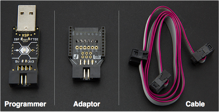

- Socket Pinout
| Mode/Pin | 1 | 2 | 3 | 4 | 5 | 6 | 7 | 8 |
|---|---|---|---|---|---|---|---|---|
| align=“center” | FTDI: | align="left” | - | align="left” | VCC | align="left” | - | align="left” |
| align=“center” | ISP: | align="left” | MISO | align="left” | VCC | align="left” | SCK | align="left” |
Note:
- DTR signal - If be enabled, high level default. When you open the serial port, it will output a 50ms low pulse, which could trigger MCU reset even if there is no 100nf capacitance connecting to MCU reset pin.
FTDI to XBee interface, ISP bonding pad reserved
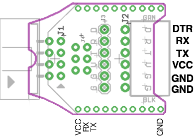
: Note: FTDI doesn't include CTS signal, it is not used in Arduino.
Connect Programmer, Adapter, eClip .etc. 
Note: You could config XSP function through serial port. Since it doesn't need to config its parameter frequently, we did following constraint to improve its work efficiency.
- After each time you open the serial port, you only could make once configuration.
- After you open the serial port, you can enter Configuration mode only if you input "NL/CR" before input any other characters. If you input other character, it will go into Work mode.
- If you want to enter Configuration mode again, you need to close and open serial port again.
XSP could be configured by any COM debug tool. We will using Arduino IDE as our example.
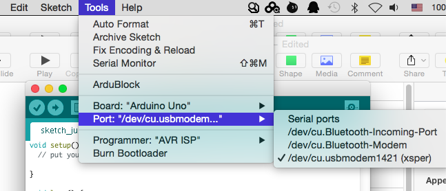
- Plug XSP into PC usb port, select COM port (Here is a MAC screen capture, different OS has different UI.)
- Open Serial monitor, Select “Both NL & CR” (Red), press “Enter” keypad or click "Send" icon to enter configuration mode. (Don't input any character before this step, or it will go into work mode);
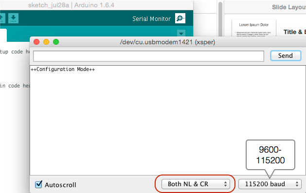
- Input “help”, config its parameter according to the help instruction;
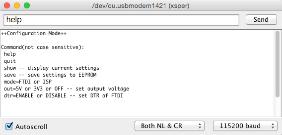
- For example, if you want to set it as ISP mode, just input "mode=isp", and watch XSP indicator LED, when it is light, it means it has entered ISP mode. (There is no reply in the serial console);
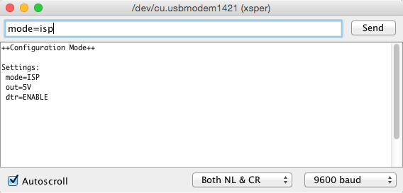
- Then, you could check the configuration by "show" command;
- Using “save” command to save the configuration parameter to EEPROM, so it will keep the configuration after power down. If you only need a temporary use, just not save, and using "quit" command to exit the configuration mode, than the configuration takes effect before it is power down;
| Note: |
- During the configuration, as long as nothing is entered over 60s, it will exit the Configuration mode, and enter into Work mode. |
There are 5 indicator LEDs on XSP Programmer, representing its working condition.
State \ LED |
FTDI |
ISP |
5V - 3V3 |
DATA |
|---|---|---|---|---|
Power on self test |
OFF |
ON |
ON - ON |
ON |
Work-FTDI |
ON@"DTR=ENABLE"; |
OFF |
FLASH |
Fast FLASH during data transmission |
Work-ISP |
OFF |
ON |
||
Configuration |
ON based on configuration |
ON based on configuration; |
N/A |
|
Failure |
Both LEDs Fast FLASH |
Fast FLASH |
| Note: |
- When it is in Failure state, please open the Serial console to check the error information. |
(Example of Arduino IDE)
- Connect XSP programmer to your target board, and plug XSP to your PC USB port;
- Please refer to https://www.arduino.cc/en/Guide/Windows#toc4
(Example of Arduino IDE)
- Connect XSP programmer to your target board, and plug XSP to your PC USB port;
- Open Ardino IDE -> Tools -> Port, select the right COM port;
- Open the Serial monitor, set the right baudrate.
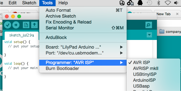
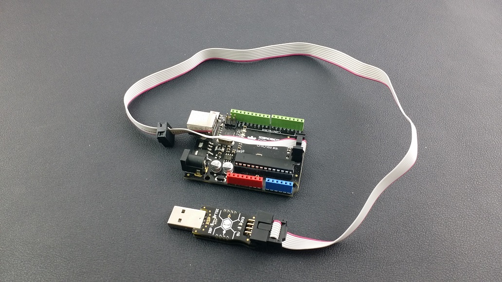
- Connect XSP programmer to your target board, and plug XSP to your PC USB port;
- Open Ardino IDE -> Tools -> Board, Select the board type;
- Open Ardino IDE -> Tools -> Port, Select the right COM port;(Do not open the COM port after this step)
- Open Ardino IDE -> Tools -> Programmer, Select "AVR ISP"
- Open Ardino IDE -> Tools -> Burn Bootloader, click
- Done!
| Note: |
- AVR ISP is using Virtual Serial Port, so please do not open the serial port in the other way, or it will lose control; You need to close the Serial monitor, and powered off and re-up electricity to the device. |
You can use avrdude command to operate the target board, (-cstk500v1)
e.g. avrdude -p atmega328p -cstk500v1 -P/dev/tty.usbmodem14111 -b57600 -t
 buy from dfrobot store or dfrobot distributor list