Veyron_Servo_Driver_(24 Channel)_(SKU_DRI0029) - jimaobian/DFRobotWiki GitHub Wiki

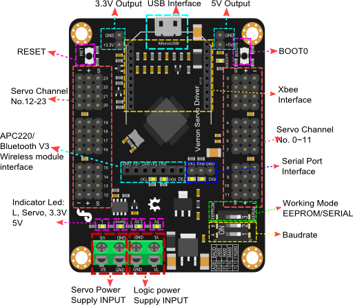
Veyron Servo Driver (24-Channel) is a multiple servo controller, especially designed for humanoid robots, spider robots, robotic arms, and many other likewise applications. The controller integrates wireless data transmission interface, which is fully compatible with DFRobot Bluetooth module, APC220 wireless data transmission module and Xbee module. The controlling modes include real-time, timer, constant speed. Veyron Servo Driver (24-Channel) is the most powerful Mirco USB servo driver with high reliability on the market. It uses a high-performance, low-power STM32F103 microcontroller as its core control unit, which has a powerful, fast execution speed, high accuracy, strong I / O drive power. It supports Futaba, Hitec, Fraser and most common servos. The servo control range could be 0 ~ 180 ° (for 360 ° continuous rotation, retrofitting is needed); It has two servo control modes: single servo control, group servo control. In group control mode, the same group can be coordinated automatically with start and stop at the same time. It will be very useful in multi-DOF biomimetic robots, which requires smooth actions.
 |
DO NOT PROGRAM THIS SHIELD! |
We have uploaded the firmware to Maple RET6 already. Please do NOT upload any sketch to the chip carelessly. Or it will be defective and cannot read any command by serial port anymore. |
- Output channels: 24 (PWM output or TTL level output);
- Servo Power: DC 4.8V ~ 6V;
- Logic Power: DC 6V ~ 12V or USB (with a resettable fuse in debugging);
- Driver Resolution: 1uS; 0.09°;
- Drive speed Resolution: 1uS/s; 0.09°/s
- Communication Interface: Micro USB /TTL serial interfaces;
- Baud rate: 2400,9600,38400,115200
- Size: 57.3 x 72.3mm
- Weight: 26g(without package)
It requires to install the driver, when you use it for the first time.
| NOTE: If you met any problem of installing the driver, you may need disable the Windows feature of Digital signature requirment, you need to disable that to install the driver. Actually, there is another way to install the driver for STM32, read at the end of the wiki > More > Share. |
- Connect Veyron Servo Driver 24-Channel to a computer via USB port(USB2.0 is better).And Open your PC Device Manager.

- Press the "reset" button, the blue light will flash six times fast, then slow blink several times.
- Press the "reset" button again, and then press to hold "BOOTO" button during blue lights flashing rapidly, until the light starts blinking slowly. The blue light will keep flashing. Now you can install the driver.
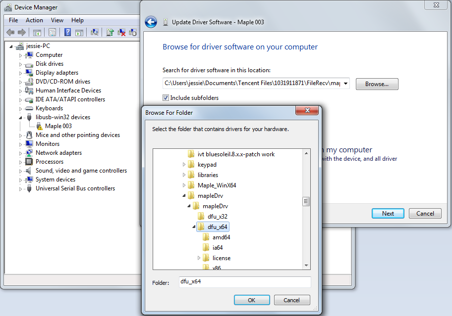
- Windows will prompt you for a driver, manually locate the directory, select mapleDrv -->dfu_x64/dfu_x32(Please select your OS bit: 64-bits or 32-bits) in the folder. Next install a virtual serial port driver:

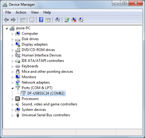
- Reset Veyron Servo Driver 24-Channel with RET button, wait for the blue light stops flashing. At this point Windows will prompt to install the driver, too. Please manually locate the directory, select mapleDrv -->serial in the folder. Until now, the driver has been installed
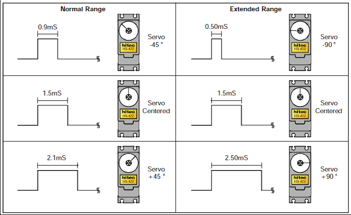
Run Time (sec) = pulse width (us) / Speed (us / sec).
e.g.The initial position is 750us, the finial position is 2250us, the speed is 1000us/s The running time;
T=(2250-750)/1000=1.5s
So the running time is 1.5s.
Device List:
- Veyron Servo Driver 24-Channel
- Micro USB cable
- TowerPro SG90 Servo
- Servo 5V power supply
- 9V power supply logic
Veyron requires an external power supply to support the servo
In this section, we will use Arduino IDE as a Serial port communication tool to control the servo. And, you also could use other Serial port software, like putty, CoolTerm etc.
Connect Micro USB cable to the Veyron Servo Driver 24-Channel, then the power indicator LED will be on. Connect an external 5V power to the VS and GND. Then switch the DIP 3 at SERIAL, USB has been defaulted to 57600 baudrate (cannot be changed), should be consistent with software.
Open you Arduino IDE, click "Tools", select your board Serial port, and open the Serial monitor.
Select "Carriage return",and the right baudrate. 
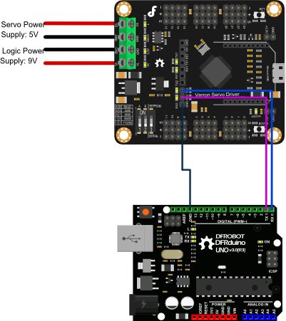
void setup() {
  Serial.begin(115200);//Set the baudrate to 115200 A:1  B:1
  delay(100);//wait for baudrate setting finished
}

void loop() {
  Serial.print("#5 P750");// Channel 5 will move to 750us within 500ms
  delay(5);               //wait for first comand transmission done, if you send
  // a long command, you'd better extend it
  Serial.print("\r");    // send Carriage Return <CR>
  delay(1000);            //wait for servo go to the set position
  Serial.print("#5 P2200");// Channel 5 will move to 2200us within 500ms
  delay(5);
  Serial.print("\r");
  delay(1000);
}#<ch> P <pw> S <spd> ...# <ch> P <pw> S <spd> T <time><cr>
- : Servo channel number, 0 - 23
- : pulse width(us), 500 - 2500; the destination position
- : single-channel speed (us/s)(Optional)
- : the whole channel speed (ms), maximum 65535(Optional)
- : carriage return, the symbol of the end, ASCII code 13 (Required)
- : Cancel the current command, ASCI code 27
#5 P1600 S750 <cr>
The servo on Channel 5 will move to 1600us position at the speed of 750us/s.
#5 P1600 T1000 <cr>
The servo on Channel 5 will move to 1600us from any position after 1000ms.
#5 P1600 #10 P750 T2500 <cr>
The Servo on Channel 5 will move to 1600us position and servo on channel 10 will move to the 750us position. They will arrive simultaneously after 2500ms. This command can coordinate multiple servo speed, even if the initial position of two servos are very far, you can make they start to rotate and stop at one specified position. This command is very suitable for humanoid bipedal robot
#<ch> PO <offset value> ... # <ch> PO <offset value> <cr>
- : Servo channel number, 0 - 23
- : 100 to-100us
- : the end of the carriage return, ASCII code 13
To rectify the pulse width of a channel, then humanoid robot could rectify the position without mechanical hardware.
#<ch> <lvl> ... # <ch> <lvl> <cr>
- : Servo channel number, 0 - 23.
- : channel output logic level high 'H' or low 'L'.
- : the symbol of the end, ASCII code 13.
The channel will output a level after received carriage return symbols in 20ms.
#3H #4L <cr>
This command makes the channel 3 output a high level(+3.3 V), Channel 4 output a low level(0V).
# <bank>: <value> <cr>
- : 0 = 8-15,2 = Channel Channel Channel 0-7,1 = 16-23.
- : decimal output (0-255), Bit0 = LSB.
This command allows the 8-bit binary write-once and simultaneously update all channels in the bank, the update will be completed within 20ms after receive carriage return symbols
# 1:123 <cr>
This command enables bank output 123 in decimalism, 123(decimal) = 01111011 (binary), bank 1 for channels 8-15, then channel 8 and 13 in bank 1 will be 0, the other channel will be 1.
Q <cr>
If servo is rotating, it will return "+", if servo has moved to a specific location, it will return "." The return value of this command will delay 50us to 5ms.
QP <ch> <cr>
- : Servo channel number, 0 - 23.
The return value is one byte (binary), which means the servo current pulse width, resolution: 10us, for example, the pulse width is 1500us, then it will return to 150 (binary). This command can query multiple servo pulse width, each servo has a byte, the return value will delay 50us to 5ms, typical value is 100us.
We have made a special software--DFServo to drive Veyron.
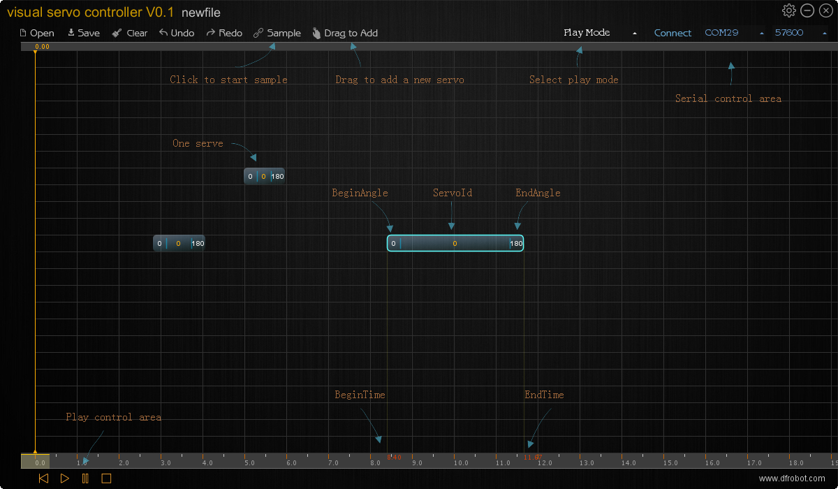 You could click here to check DFServo tutorial.
void setup() {
  Serial.begin(115200);//Set the baudrate to 115200 A:1  B:1
  delay(100);//wait for baudrate setting finished
}

void loop() {
  Serial.print("#5 P750");// Channel 5 will move to 750us within 500ms
  delay(5);               //wait for first comand transmission done, if you send
  // a long command, you'd better extend it
  Serial.print("\r");    // send Carriage Return <CR>
  delay(1000);            //wait for servo go to the set position
  Serial.print("#5 P2200");// Channel 5 will move to 2200us within 500ms
  delay(5);
  Serial.print("\r");
  delay(1000);
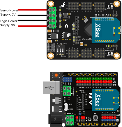
}
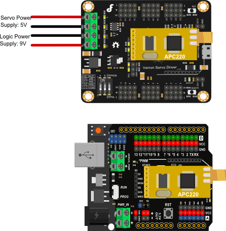
| '''Q 1. '''Why I cannot control servo by external serial port, I mean when I use BT module or by arduino Uno serial port? I can do it through pc's serial monitor. |
'''A. '''Hello, it's for the baud rate setting. Have you noticed the baudrate setting switch on the corner of the board. Is it in the right place, e.g. if your code is 115200, then the 3 switchs should be in the position as:A1, B1, SERIAL. Besides, the switch are not good to use, you might need a little strenth to poke it from one side to the other side to make sure it is connected firmly. We will update the switch in the next version.
| '''Q 2. '''I have a Veyron Servo Controller that I flashed a sketch to, and now it does not respond to the Visual Servo Controller software. Where can I download the factory sketch? |
'''A. '''Hi, click here to download the factory sketch, and you can upload it to Maple RET6 flash by Maple IDE.
-
Share
- Arduino STM32, this method can help you install all the drivers you need, besides, it could allow you to program it using Arduino IDE if you'd like to. Read the warning
 get it from dfrobot store or dfrobot distributor.
category: Product Manual category: DRI Series category: Shield