Veyron_1x5A_Brushless_Motor_Driver_SKU__DRI0014 - jimaobian/DFRobotWiki GitHub Wiki
![]()
The new Veyron brushless motor controller DFBLDC(1x5A) provides 3 different kinds Input modes(PPM、UART、ANALOG) it is especially designed for brushless motors which are widely used in robotics industry because of their high-performance and good reliability.
- Model Size:74mm X 40mm X 19mm
- Moedl Weight: 50g
- Input Voltage: 8
30V(1224V recommended) - Operating Temperature: -30~+70℃
- Input modes: PPM、UART、ANALOG(0~5V)
- Baudrate Types:1200/2400/4800/9600/14400/19200/28800/38400/57600/115200
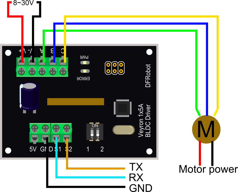
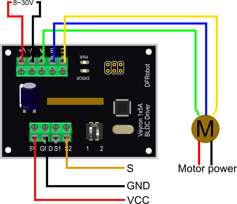
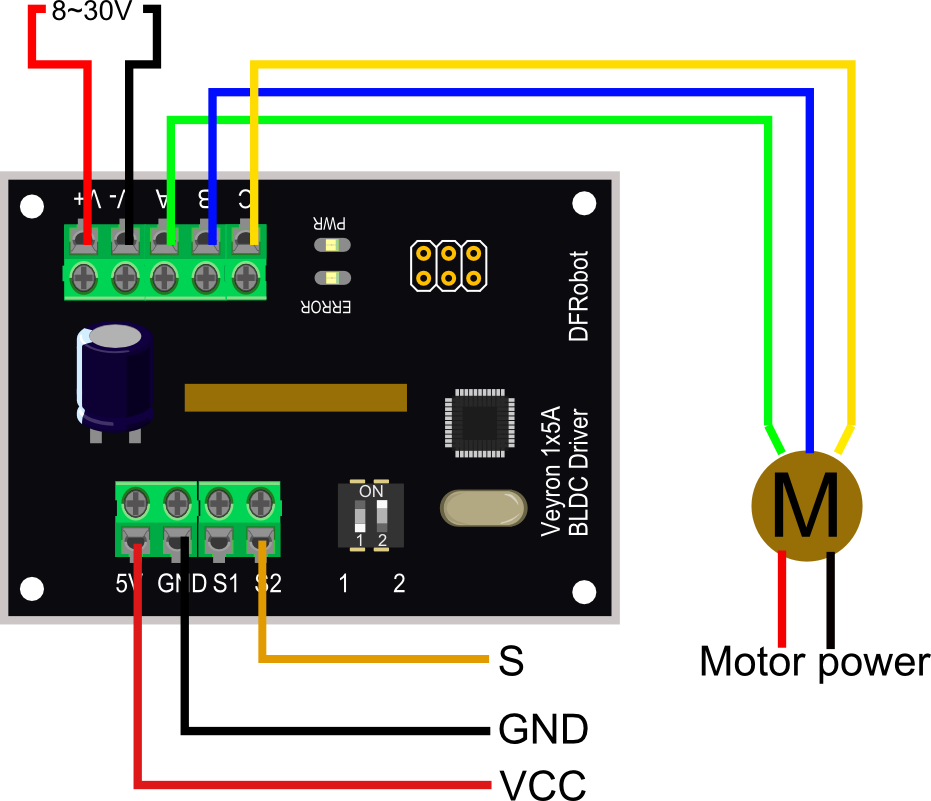
For UART, PPM and ANALOG Mode, the communication depends on "S1" and "S2". The ports are assigned as the table shown below:
| Toggle Switch State | Working Mode |
|---|---|
| 1: OFF 2:OFF | UART |
| 1: OFF 2:ON | PPM |
| 1: ON 2:OFF | ANALOG |
| 1: ON 2:ON | RESERVED |
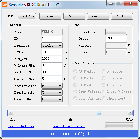
Software: Sensorless BLDC Driver Tool

Step1: Please pay attention on "RX" and "TX". This is the connection with USB-TTL convertor. If you want to use UNO, please exchange RX and TX.
Step2: Open the software, and select the correct COM port.
 step3: click "read" to read the motor status.it will show "Read successfully" on the bottom.
Step4: Move the slider to control the speed and direction of the motor.
For the further detail, please check the Device Manual(Link).
It is compatible with standard aero-model PPM interface, and you can also set the value of the width and the amplitude of the pulse signal yourself. Values between the minimum value and the medium value stand for clockwise rotation, and those between the medium value and the maximum value stand for counter-clockwise rotation, while the medium value stands for stop.

//Name: Sensorless BLDC Driver V1-example code in PPM Mode
//Version: v0.1;
//Author: Barry from DFrobot;
// This code can be used to control the brushless motor driver in the PPM Mode;
// Details in User manual;
// make sure the toggle switches on the driver are in the right position for PPM Mode;
#include <Servo.h>
Servo mymotor;
void setup()
{
mymotor.attach(9);
}
void loop()
{
mymotor.writeMicroseconds(2000); //motors rotating in clockwise direction with the highest speed;
delay(5000);
mymotor.writeMicroseconds(1000); //motors rotating in counter-clockwise direction with the highest speed;
delay(5000);
mymotor.writeMicroseconds(1500); //motors stop;
delay(5000);
}02.5V input stands for clockwise rotation, and 2.55V input stands for counter-clockwise rotation, while 2.5V stands for stop.

It is using Arduino PWM output to simulate an analog value change.
int Motor_pin = 9;
void setup()
{
pinMode(9, OUTPUT);
}
void loop()
{
int value;
  for(value = 0 ; value <= 255; value+=5)
  {
    analogWrite(Motor_pin, value);   //PWM Speed Control
    delay(100);
  }
}- ERROR: Lower MOS of phase A broken:
- It requires 8
30V power supply(1224V recommended), if your power is less than 8V, it will show error. - Motor: please connect motor to the driver, or it will still show “error”.
- Please connect the motor power interface (8~30V) first, and Arduino board later
- It requires 8
 shopping veyron 1x5a brushless motor driver (dri0014)
category: Product Manual category: DFR Series category: Hardware-Mechanical