Triple_Axis_Accelerometer_MMA7361_(SKU__DFR0143) - jimaobian/DFRobotWiki GitHub Wiki

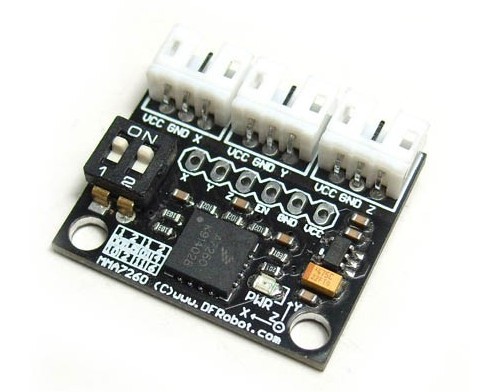
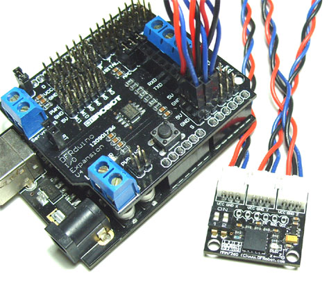
The MMA7361 from Freescale is a very nice sensor with easy analog interface. The MMA7361 is a 3.3V part and outputs an analog voltage for each of the three outputs. This voltage is in ratio to the measured acceleration and to the supply voltage (ratiometric). It has selectable sensitivity by dip switch. You will need some extra hardware to convert this analog signal to a usable digital one. The Arduino is really good option for it. This break board is especially designed for Arduino which has 3 JST connector that can be easily plug into our IO/Sensor expansion board.
- Voltage:3.3-8V
- Selectable sensitivity:±1.5g/6g
- Low power:500μA @ measurement mode,3μA @standby ;
- High sensivity: 800 mV/g @ 1.5g;
- Interface:Analog Output
- Low pass filter
- Size:23x26mm
- Weight: 5 gram

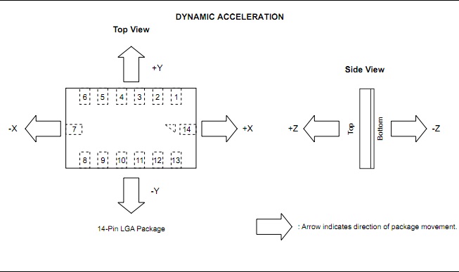
The diagram consist of the following items:
Here is a tutorial to show how to use it. We've done a program to treat this Triple Axis Accelerometer as a Gyro. We can measure the angle between triple axis on the device and the direction of gravity. With these three-angle information, the location of plane is uniquely described in 3D space.
| g-Select | g-Range | Sensitivity |
| 0 | 1.5g | 800mV/g |
| 1 | 6g | 206mV/g |
g-Selection Pin Description
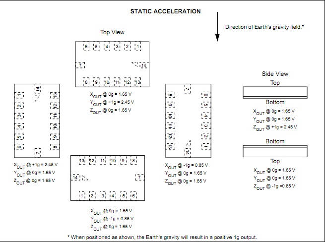
As we can see from the above(choose g-range 1.5g),each axis turns out to be 1.65V when it is @0g.It is to say that this axis is level at this moment.When the axis is on the direction of earth's gravity field,it is affected by the gravity of 1g(max).It turns to be 2.45V.Also it turns to be 0.85V when on the against direction.
- analogRead(x)-->(2)vol_x(v)
The working voltage we set for MMA is 5V which will show as 1024 in the serial monitor.So we should convert the analog to voltage.vol_x=analog_x*5/1024.

 2. vol_x-->add_x(v)
When the axis is level,it turns to be 1.65v.So we need to subtract this amount to get the added gravity.add_x=vol_x-1.65.
 - add_x-->g_x We choose g-range 1.5g for MMA.To the g-range table,its sensitivity is 800mv/g.So we just need to make a division.g_x=add_x/0.8.
- g_x-->degree It is the gravity of 1g that affects the axis amount.It is to say that each axis amount (g)is an component of 1g.So we can use a Inverse trigonometric function to convert it. Degree_x=asin(g_x) *180.0/PI.
Attention: Not each axis shows exactly 1.65v when it is level.So we need to make a compensation for it.But it also has a range for this.
First, we should read the voltage out from this accelerometer to slightly adjust the value of zero force voltage. We know the ideal value is 1.65. However, from the real examination, we found that this value was biased. So before we do any useful project, we must verify the genuine zero force voltage carefully according to practical device.
//Arduino Sample Code
//Developed by Yuki from DFRobot.com
//Last Modified 02/08/2012
//Version 1.0 or lower

void setup()
{
  Serial.begin(57600);
}
int analog_x,analog_y,analog_z;
float vol_x,vol_y,vol_z;

void loop()
{
 analog_x=analogRead(0);
 analog_y=analogRead(1);
  analog_z=analogRead(2);
  vol_x=analog_x*5.0/1024;//convert analog_x-->voltage value(v)
  vol_y=analog_y*5.0/1024;
  vol_z=analog_z*5.0/1024;
    Serial.print("x:");
  Serial.print(vol_x);
  Serial.print(" y:");
  Serial.print(vol_y);
  Serial.print(" z:");
  Serial.println(vol_z);
  delay(200);
}
So statistically, we have the range of triple axis voltage data. vol_x=: 0.83 - 2.41, vol_y=: 0.96 - 2.53, vol_z=: 0.72 - 2.23 And we choose appropriate zero force voltage according to detection data: vol_x=:1.62, vol_y=:1.74, vol_z=:1.48 Then, we use mathematical function arcsin to map the corresponding angle. Finally, we have the following codes.
//Arduino Sample Code
//Developed by Yuki from DFRobot.com
//Modified by Michael from DFRobot.com
//Last Modified 02/15/2012
//Version 1.0 or lower

void setup()
{
  Serial.begin(57600);
}
int analog_x,analog_y,analog_z;
float vol_x,vol_y,vol_z;
float add_x,add_y,add_z;
float g_x,g_y,g_z;
float degree_x,degree_y,degree_z;
void loop()
{
 analog_x=analogRead(0);
 analog_y=analogRead(1);
  analog_z=analogRead(2);
  vol_x=analog_x*5.0/1024;//convert analog_x-->voltage value(v)
  vol_y=analog_y*5.0/1024;
  vol_z=analog_z*5.0/1024;
 //range x: 0.83 - 2.41    1.62
 //      y: 0.96 - 2.53    1.74
 //      z: 0.72 - 2.23    1.48
  add_x=vol_x-1.62;//calculate the added x axis voltage value
  add_y=vol_y-1.74;
  add_z=vol_z-1.48;
  g_x=add_x/0.8;//calculate the gram value
  g_y=add_y/0.8;
  g_z=add_z/0.8;

  if(g_x<=1&&g_x>=-1) //We use this condition to prevent the overflow of asin(x).( If x>1 or x<-1, asin(x)=0)
  {
  degree_x=asin(g_x)*180.0/PI;//calculate the degree value
  degree_y=asin(g_y)*180.0/PI;
  degree_z=asin(g_z)*180.0/PI;
  }
  //fix the overflow condition
  if(g_x>1)
  degree_x=90;
    if(g_x<-1)
  degree_x=-90;
    if(g_y>1)
  degree_y=90;
    if(g_y<-1)
  degree_y=-90;
    if(g_z>1)
  degree_z=90;
    if(g_z<-1)
  degree_z=-90;
 //#########################
 //print
  Serial.print("x:");
  Serial.print(degree_x);
  Serial.print(" y:");
  Serial.print(degree_y);
  Serial.print(" z:");
  Serial.println(degree_z);
  delay(200);

} shopping triple axis accelerometer mma7361 (sku: dfr0143)
category: Product Manual category: DFR Series category: Source