Tri Axis_Gyro_Breakout SD740_(SKU__SEN0095) - jimaobian/DFRobotWiki GitHub Wiki
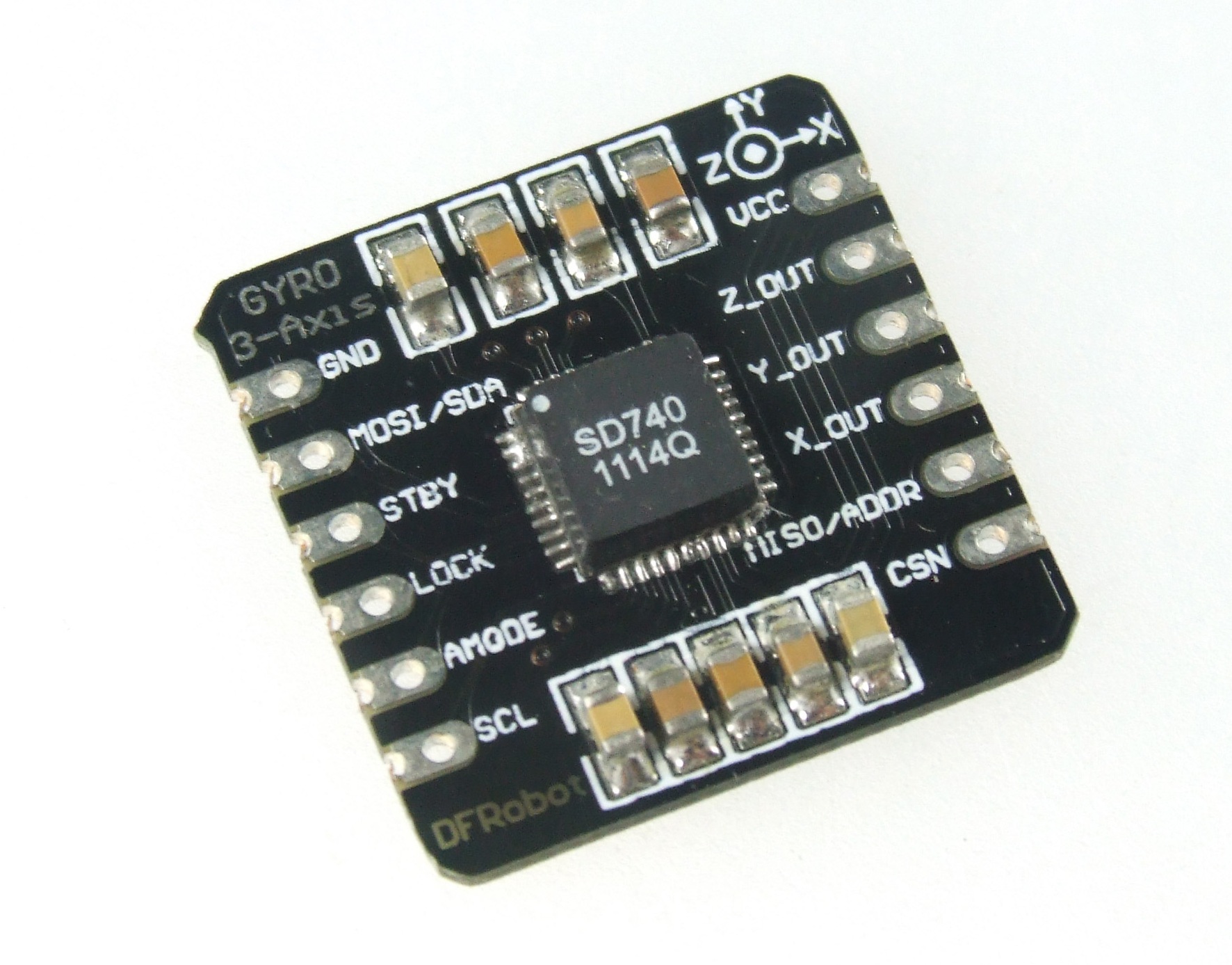 this is a breakout board for the tri-axis sd740 gyroscope. the sd740 inertial module integrates a tri-axial micro machined gyroscope together with a signal conditioning asic in 0.18um cmos technology. the asic provides configurable output filters allowing the user to customize both gain and bandwidth. zero rate bias can be adjusted as well. the sensor elements are forced to a primary vibration. the gyro features a primary output with a +/-1024 degrees/s full scale range (digitally scalable down to +/-64 degrees/s). gyroscope signal conditioning is fully performed in the digital domain ensuring superior signal stability and performance. the signal processing operates at high data rates resulting in a high output value refresh rate of less than 100us.
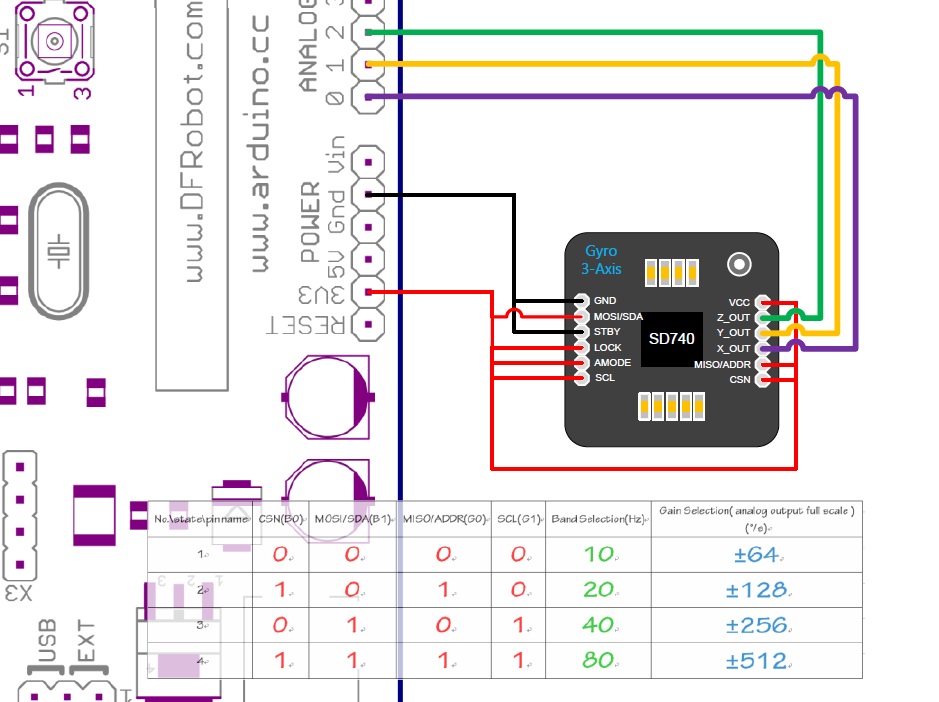
The module is designed to operate with 3 interfaces: 1. Digital SPI 2. Digital I2C 3. Analog Outputs Configuration pads allow the user to select the proper interface.
Warning: Please only use 3.3v to supply power to the Gyroscope.
* SD740 Triple Axis Gyroscope
 shopping (sku:tel0038)
category: Product Manual category: TEL Series
- 2.6V to 3.3V power supply, 5.2mA current consumption
- <100uA standby current; power off mode available.
- Temperature operating range -40 degrees to +85 degrees
- +/-1024 degrees /s full scaly dynamics (digitally scalable down to +/-64 degrees/s)
- Ratio metric analog outputs and digital outputs (SPI and I2C)
- Digital bus operating from 1.8V t 3.3V
- Fully calibrated over the whole operating temperature range
- Continuously working self diagnosis
- Fully digital processing for rate signals and gyroscope control loops
- Size: 21x21x3(mm)
- Data Sheet
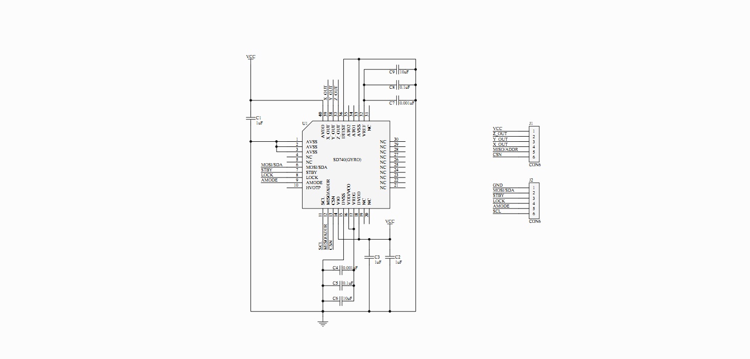
/*
Gyroscope SD740 I2C Mode

 Version 1.0  Lauren <[email protected]>

 Operating Supply Voltage           V    2.6 - 5% - 3.3 + 5%
 Full Scale Range (digital output) °/s  1024
 Sensitivity Accuracy               %    ± 5
 Sensitivity Error Over Temperature %    ± 5
 Signal Update Rate                 KHz  10
 SPI Communication Speed            KHz  400

 Full scale range is factory defined. Please contact SensorDynamics for setting different ranges. Maximum full scale
 factor is 4096°/s
 Bandwidth is factory defined. Please contact SensorDynamics for setting different ranges. Maximum bandwidth is
 150Hz

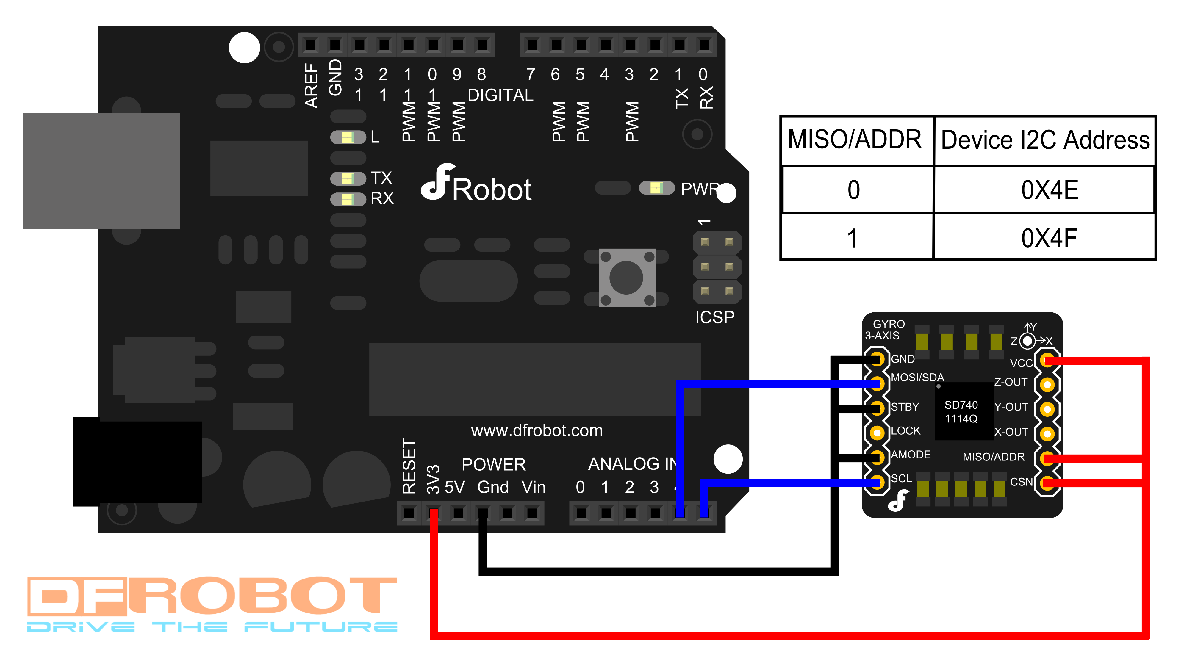
 I2C Address setting

 Pin          state        Device address

 MISO/ADDR    LOW          0x4E
 MISO/ADDR    HIGH         0x4F

 */

#include <Wire.h>
#define DEVICE 0x4F

byte buff[20] ;    //6 bytes buffer for saving data read from the device
char str[128];                      //string buffer to transform data before sending it to the serial port

//I2C Address A7

void setup(){

  Wire.begin();        // join i2c bus (address optional for master)
  Serial.begin(57600);  // start serial for output

}


void loop(){

  int regAddress = 0x00;    //first axis-acceleration-data register on the ADXL345
  int x, y, z;

  readFrom(byte(DEVICE), regAddress, 8, buff);//receive data

  x = (((int)buff[2]) << 8) | buff[3];
  y = (((int)buff[4]) << 8) | buff[5];
  z = (((int)buff[6]) << 8) | buff[7];

//  we send the x y z values as a string to the serial port
//
  sprintf(str, "%d %d %d", x, y, z);
  Serial.print(str);
  Serial.print(10, BYTE);

//  It appears that delay is needed in order not to clog the port
  delay(100);

}

//---------------- Functions
//Writes val to address register on device
void writeTo(int device, byte address, byte val) {

  Wire.beginTransmission(device); //start transmission to device
  Wire.send(address);        // send register address
  Wire.send(val);        // send value to write
  Wire.endTransmission(); //end transmission

}

//reads num bytes starting from address register on device in to buff array
void readFrom(int device, byte address, int num, byte buff[]) {

  Wire.beginTransmission(device); //start transmission to device
  Wire.send(address);        //sends address to read from
  Wire.endTransmission(); //end transmission

  Wire.beginTransmission(device); //start transmission to device
  Wire.requestFrom(device, num);    // request 6 bytes from device

  int i = 0;
  while(Wire.available())    //device may send less than requested (abnormal)
  {
    buff[i] = Wire.receive(); // receive a byte
    i++;
  }
  Wire.endTransmission(); //end transmission

//  for(int j = 0;j < i;j ++){    //output all received bytes
//    Serial.print(buff[j],HEX);
//    Serial.print("\t");
//  }
//  Serial.print(10, BYTE);

}
/*
Gyroscope SD740 SPI connection

 Version 1.0  Lauren <[email protected]>

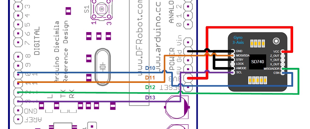
 Pin connection to the Arduino board:

 CSN         ->   digital pin 10(D10)
 MOSI/SDA    ->   digital pin 11(D11)
 MISO/ADDR   ->   digital pin 12(D12)
 SCL         ->   digital pin 13(D13)

 Operating Supply Voltage           V    2.6 - 5% - 3.3 + 5%
 Full Scale Range (digital output) °/s  1024
 Sensitivity Accuracy               %    ± 5
 Sensitivity Error Over Temperature %    ± 5
 Signal Update Rate                 KHz  10
 SPI Communication Speed            MHz  40

 Full scale range is factory defined. Please contact SensorDynamics for setting different ranges. Maximum full scale
 factor is 4096°/s
 Bandwidth is factory defined. Please contact SensorDynamics for setting different ranges. Maximum bandwidth is
 150Hz

 */


#include <SPI.h>

#define DataRegister 0x00
#define CS_Pin 10            //chip selection pin

char receiveData[128];        //data array
int x,y,z;
float xg,yg,zg;
float absHeading = 0;         // calculate the absolute heading
unsigned long iTime = 0;

void setup(){

  Serial.begin(57600);

  SPI.begin();
  SPI.setDataMode(SPI_MODE0);

  pinMode(CS_Pin, OUTPUT);// init the chip selection pin
  digitalWrite(CS_Pin, HIGH);

  checkGyroStatus();

}

void checkGyroStatus(){

  readRegister(20,1,receiveData);
  Serial.print("check lock state:\t");
  Serial.println(receiveData[0],BIN);//bin; 110 means works well

  if(bitRead(receiveData[0],1) == 0 || bitRead(receiveData[0],2) == 0){
    Serial.println("Chip start error! You could reset the arduino board");
    while(1){
    }
  }

  readRegister(70,1,receiveData);
  Serial.print("check standby bit:\t");
  Serial.println(receiveData[0],BIN);//check bit0 0->normal 1->standby

}

void loop(){

  readRegister(DataRegister, 6, receiveData);

  x = ((int)receiveData[0]<<8)|(int)receiveData[1];
  y = ((int)receiveData[2]<<8)|(int)receiveData[3];
  z = ((int)receiveData[4]<<8)|(int)receiveData[5];

  float scale = 0.03125;// scale: 1024 / 2^15

  xg = x * scale;
  yg = y * scale;
  zg = z * scale;
  float pastTime = float(micros() - iTime) / float(1000000);
  absHeading += zg * pastTime;
  iTime = micros();

  /*
  Serial.print(x, DEC);
  Serial.print(',');
  Serial.print(y, DEC);
  Serial.print(',');
  Serial.println(z, DEC);
  Serial.print((float)xg,2);
  Serial.print("\t");
  Serial.print((float)yg,2);
  Serial.print("\t");
  Serial.print((float)zg,2);
  Serial.println(" °/s");
  */
  Serial.print("Heading:");
  Serial.println(absHeading);//Axis Z absolute heading


  delay(10);

}

void writeRegister(char registerAddress, char value){

  digitalWrite(CS_Pin, LOW);
  SPI.transfer(registerAddress);
  SPI.transfer(value);
  digitalWrite(CS_Pin, HIGH);

}


void readRegister(char registerAddress, int numBytes, char * values){

  char address = 0x80 | registerAddress;
  digitalWrite(CS_Pin, LOW);
  SPI.transfer(address);
  for(int i=0; i<numBytes; i++){
    values[i] = SPI.transfer(0x00);
  }
  digitalWrite(CS_Pin, HIGH);

}
/*
Gyroscope SD740
Analog output mode
Display the gyro output volts

Version 1.0  Lauren <[email protected]>

Full Scale Range (analog outputs)   °/s   - 64, 128, 256, 512 -
Operating Supply Voltage              V     2.6 - 5% - 3.3 + 5%

Analog Output Range             Vdd * 0.1       -       Vdd * 0.9
Analog Output Sensitivity       V / (°/s)      (Vdd / 2) / Full Scale
Analog Output @ 0°/s           Vdd/2 � 0.05    -       Vdd/2 + 0.05
Analog Output Resolution bit    10

Full scale range is factory defined. Please contact SensorDynamics for setting different ranges. Maximum full scale
factor is 4096°/s
Bandwidth is factory defined. Please contact SensorDynamics for setting different ranges. Maximum bandwidth is
150Hz
*/


void setup(){

  Serial.begin(57600);

}

void loop(){

  float voltX,voltY,voltZ;

  voltX = analogRead(0) * 5.0 / 1024.0;
  voltY = analogRead(1) * 5.0 / 1024.0;
  voltZ = analogRead(2) * 5.0 / 1024.0;

  Serial.print("x: ");
  Serial.print(voltX,5);
  Serial.print(" v\ty: ");
  Serial.print(voltY,5);
  Serial.print(" v\tz: ");
  Serial.print(voltZ,5);
  Serial.println(" v\t Reference: 3.3v");

  delay(50);

}
RAR file with all sample codes, data sheets, and wiring diagrams.
 shopping (sku:sen0095)
category: Product Manual category: SEN Series
 SPI Connection
 Analog Connection
 Sample Code