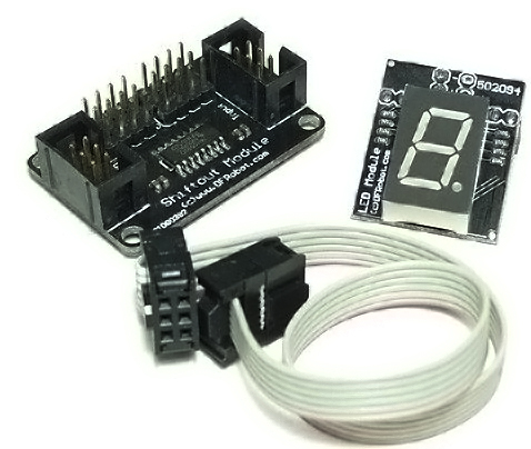
Shift_out_LED_kit_(SKU_DFR0089) - jimaobian/DFRobotWiki GitHub Wiki
Introduction
 this shiftout led kit includes a very simple and small led display module. it makes it possible for you to directly connect many 7-segment led modules in a chain. so you could diy a simple timer or a clock display , and many other devices that require the use of 7 segment LEDs.
Specification
- supply power:5V
- Interface: SPI
- Common Anode
- Digital Bits: 1
- number of connecting:over 16
- Directly connected with the interface shield
- Compatible with the SPI LED Module 8 Digital (Arduino Compatible)
- size:41x30x25mm
Pin Usage
Shiftout register:Digital pins 3, 8, and 9
Sample Code
//Pin connected to latch pin (ST_CP) of 74HC595
const int latchPin = 8;
//Pin connected to clock pin (SH_CP) of 74HC595
const int clockPin = 3;
////Pin connected to Data in (DS) of 74HC595
const int dataPin = 9;
byte Tab[]={
  0xc0,0xf9,0xa4,0xb0,0x99,0x92,0x82,0xf8,0x80,0x90,0xff};
void setup() {
  //set pins to output because they are addressed in the main loop
  pinMode(latchPin, OUTPUT);
  pinMode(dataPin, OUTPUT);
  pinMode(clockPin, OUTPUT);
  Serial.begin(9600);
  Serial.println("reset");
  for(int i = 0;i < 10; i++){
    digitalWrite(latchPin, LOW);
    shiftOut(dataPin, clockPin, MSBFIRST, Tab[i]);
    digitalWrite(latchPin, HIGH);
    delay(500);
  }
}
void loop() {
  if (Serial.available() > 0) {
    // ASCII '0' through '9' characters are
    // represented by the values 48 through 57.
    // so if the user types a number from 0 through 9 in ASCII,
    // you can subtract 48 to get the actual value:
    int bitToSet = Serial.read() - 48;
    // write to the shift register with the correct bit set high:
    digitalWrite(latchPin, LOW);
    // shift the bits out:
    shiftOut(dataPin, clockPin, MSBFIRST, Tab[bitToSet]);
    // turn on the output so the LEDs can light up:
    digitalWrite(latchPin, HIGH);
  }
}

shopping shift out led kit (sku:dfr0089)
category: Product Manual category: DFR Series category: Components category: source