SIM808_with_Leonardo_mainboard_SKU_DFR0355 - jimaobian/DFRobotWiki GitHub Wiki
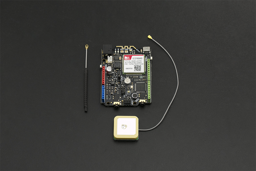
SIM808 with Leonardo mainboard is the latest Arduino card developed for multi-purpose by DFRobot. The SIM808 module onboard is an integrated quad-band GSM/GPRS and GPS satellite navigation technology module. 4-layer PCB design makes the powerful card into an UNO size, this can saves time and cost for you.
This SIM808 we chosen is the latest version, compared with the existing SIM808 module on the market, the new module has a better stability. However, you may have to pay attention that the AT command of the GPS is not compatible with the old version of the SIM808 module.
Applications: GPRS network nodes, remote communications, GPS positioning and monitoring in real time, the Internet of things(IoT).
- AVR Arduino microcontroller: ATmega32u4 (Bootloader: Arduino Leonardo)
- Operating voltage: 5V
- Input Voltage: 5V(USB) / 7
23V(Vin) / 3.54.3V(BAT) - Digital I/O pins: 20 (7 PWM: 3,5,6,9,10,11,13)
- Analog Input pins: 12
- Flash: 32 KB (bootloader: 4KB)
- SRAM: 2.5 KB
- EEPROM: 1 KB
- Clock Speed:16 MHz
- GSM module: SIM808 GSM/GPRS/GPS module
- Quad-band 850/900/1800/1900MHz – 2G GSM network
- GPRS multi-slot class 12/10
- GPRS mobile station class B
- Compliant to GSM phase 2/2+
- Class 4 (2 W @ 850/900MHz)
- Class 1 (1 W @ 1800/1900MHz)
- Bluetooth: Compliant with 3.0 + EDR (Not open in this version)
- Time-To-First-Fix
- Cold starts: 30s (typ.)
- Hot starts: 1s (typ.)
- Warm starts: 28s (typ.)
- Accuracy: Horizontal position <2.5m CEP
- Update rate: 5Hz
- Control: AT command (GSM07.07, 07.05 and SIMCom enhanced AT commands)
- Dimension: 73*54mm
- Weight: 50g
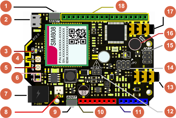
 Arduino standard digital pins
 *12 Battery Usage:
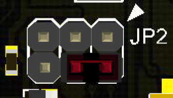
- If you attached a 3.7V Li-Battery as power supply, remember to remove the Jumper from NO-BAT (Num.12) or it will reduce the battery's life.
- Even USB connection, please remove the jumper cap.
- If you don't connect USB port or VIN power supply, make sure the jumper connected.
 NOTE: *9 BOOT
- “Boot” is the power switch, short-press to startup and long-press 3s to shutdown the device.
 NOTE: *Arduino D12 pin
- Arduino D12 pin has been connected to the module power switch. You can set the pin HIGH/LOW to turn the SIM808 module ON/OFF in code.
- The D12 pin will become inactive if the board is powered through a VIN pin by a 7-23V DC power supply, and SIM808 will auto startup in this case.
: NOTE: *17 MIC jack The MIC jack shares the same traces as the onboard MIC, so if you insert an external microphone, MIC (16) will become inactive.
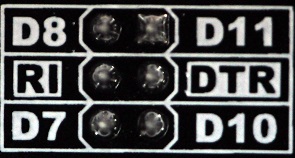
This port gets the working state of the board in code. By connecting the Arduino digital pins to DTR or RI, you can read the text info on the board's back. e.g. If I connect D8 to RI, then I could know RI pin state by writing this line in code:
   RI_state = digitalRead(8);
// remember the setup(): pinMode(8, INPUT);
1. DTR Description
DTR - Data terminal ready. The user can control the SIM808 module to enter or exit sleep mode(AT+CSCLK=1) by DTR signal or by pulling down the DTR pin. The serial port will become active after the DTR pin is pulled to LOW for 50ms.
:'''2. RI Description '''
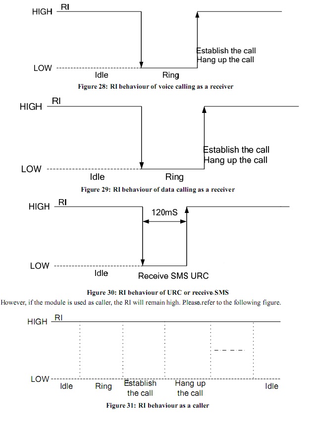
RI - Ring Indicator. The behavior of the RI pin is shown in the following table when the module is used as a receiver:
 |
                                                                                     |---------------|----------------------------------------------------------------------------------------------------------------------------------------------------------------------------------|
                                                                                     | ''' State ''' | '''RI response '''                                                                                                                                                               |
                                                                                     | Standby       | HIGH                                                                                                                                                                             |
                                                                                     | Voice Call    | The pin is changed to LOW. When any of the following events occur, the pin will be changed to HIGH:

                                                                                                      1.  Establish the call
                                                                                                      2.  Hang up the call                                                                                                                                                              |
                                                                                     | Data Call     | The pin is changed to LOW. When any of the following events occur, the pin will be HIGH:

                                                                                                      1.  Call established
                                                                                                      2.  Call hang up                                                                                                                                                                  |
                                                                                     | SMS           | The pin is changed to LOW, and kept low for 120ms when a SMS is received. Then it is changed to HIGH.                                                                            |
                                                                                     | URC           | The pin is changed to LOW, and kept low for 120ms when some URCs are reported. Then it is changed to HIGH. For more details, please refer to **SIM808_Hardware Design_V1.00**. |  |
The user can control the SIM808 module to enter or exit sleep mode (AT+CSCLK=1) by DTR signal. When DTR is high level and without interrupt (on air and hardware such as GPIO interrupt or data in serial port), SIM808 will enter sleep mode automatically. In this mode, SIM808 can still receive paging or SMS messages from the network but the serial port is not accessible.
| NOTE: The user must shut off the power supply of GPS, and then the AT commands about the power saving mode can be executed correctly, and current consumption will be lower. |
There are three functionality modes, which are set by the AT command AT+CFUN=\. The command provides the choice of the functionality levels \=0, 1, 4.
- Current consumption of function modes
| **level** | **Description** | - - Current consumption(uA)** |
| AT+CFUN=0 | minimum functionality. | 869.5 |
| AT+CFUN=1 | full functionality (default). | 1400 |
| AT+CFUN=4 | flight mode (disable RF function). | 922.5 |
Minimum functionality mode minimizes the current consumption to the lowest level. If SIM808 is set to minimum functionality by AT+CFUN=0, the RF function and SIM card function will be disabled. In this case, the serial port is still accessible, but all AT commands correlated with RF function and SIM card function will not be accessible.
===Sleep Mode (AT+CSCLK=1) === When the GPS function is shut off, the user can control SIM808 module to enter or exit the sleep mode (AT+CSCLK=1) by DTR signal. When DTR is in high level and without interrupt (on air and hardware such as GPIO interrupt or data in serial port), SIM808 will enter sleep mode automatically. In this mode, SIM808 can still receive paging or SMS messages from the network, but the serial port is not accessible.
| NOTE: For SIM808, it requests to set AT command: AT+CSCLK=1 and ensure DTR at high level to enable the sleep mode; the default value is 0, which can not make the module to enter sleep mode. |
When SIM808 is in sleep mode (AT+CSCLK=1), the following methods can wake it:
- Pull down the DTR pin. The serial port will become active after the DTR pin is pulled to low level for 50ms.
- When a voice or data call is received over the network
- When an SMS message is received over the network
- When an external interrupt is received
- When the VBUS pin is charged
SIM808 includes an integrated charging circuit for Li-Ion batteries which makes it very convenient for any user applications that support battery charging. The maximum charge current is 1A. The following steps walk you through how to use this feature:
- Remove the jumper Cap from "NO BAT?"
- Connect a 3.7V lithium battery to the BAT interface
- Connect the mainboard to your computer via a USB cable and download the debugging code
- Short press button BOOT to boot the module
- Send command AT+ECHARGE=1 through serial Assistant/Arduino Serial Monitor to set the module into charging mode. (Port setting: Carriage return, Baud Rate: 115200)
- Connect an external DC power supply 7-23V to VIN power interface. If it fails to register, disconnect and reinsert it.
After the five steps above, you can query the battery and charging status by sending AT+CBC.
For more details please refer to the AT instruction manual (Bottom of this page > "More").
In this section we will do some basic tasks on the board via AT commands. More AT command can be found at the end of the page @ More> Document> AT commands.
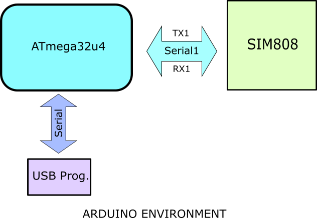
| **Note**: SIM808 mainboard is using Arduino Leonardo. This microcontroller has two serial ports. Serial0 (Serial) is used to communicated with USB port; Serial1 is used to communicated with SIM808 GSM module. Since USB port does not directly connect to the SIM808 port. We need upload a debug code to setup the communication |
/*
 * The sketch here will make Leonardo exchange
 * data between the USB serial port and SIM808 module.
*/

void setup() {
  Serial.begin(115200); //initialize Serial(i.e. USB port)
  Serial1.begin(115200); //initialize Serial1
}

void loop() {
  //If Serial1 receive data, print out to Serial
  while (Serial1.available()) {
    Serial.write(Serial1.read());
  }
  //If Serial receive data, print out to Serial1
  while (Serial.available()) {
    Serial1.write(Serial.read());
  }
  delay(1);  //delay for a short time to
  // avoid unstable USB communication
}- SIM808 with Leonardo mainboard x1
- GSM & GPS Antennas (Included) x1
- External power supply (7-23V, DC) x1
- SIM card (GSM/GPRS) x1
- Micro USB Cable x1
- Coolterm or DF Serial Debugger by Lisper, we use the second one in the wiki.
- Arduino IDE V1.5.* Click to Download Arduino IDE
- 3.7V Lithium Battery x1
- Smartphone Headset to PC Adapter x1
- Earphone x1
-
Install the SIM card in the sim slot on the back of the board
- Make sure your SIM card is available, and you can put the SIM card into the socket or get it out by sliding the metal lock.
-
Install the GPS & GSM antennas on the board
-
Connect with PC and power supply
- There are three ways to supply the power:
- Through 7~23V power supply jack
- Through VIN pin on board
- Remove the jumper on NO BAT?, and connect a 3.7V Lithium Battery to BAT jack
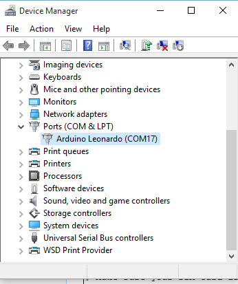
- After connecting the board to PC by an USB cable, the board shows up as Leonardo automatically if you have installed the Arduino by .exe file, or you will need to install the driver manually
- There are three ways to supply the power:
-
BOOT SIM808 by pressing the BOOT white button for 2 seconds if the NET indicator LED is OFF.
-
Upload the Debugging Code above to Leonardo.
|  |  |
Please choose the board and serial port for the main board, then open your Arduino Serial Monitor, and choose Baud Rate@ 115200, Format@ Carriage Return, you can also use other software or even wireless module.

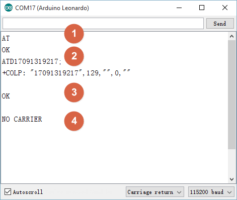
- Send AT to enter AT mode, you will get OK, or please check the serial monitor setting or if the NET led is flashing every 3 seconds.
- Send ATD170****9217; to make a call, do not forget the ";" in the end;
- If accepted, you will see OK.
- If rejected, you will see NO CARRIER.
===Answer/Reject an Incoming Call===
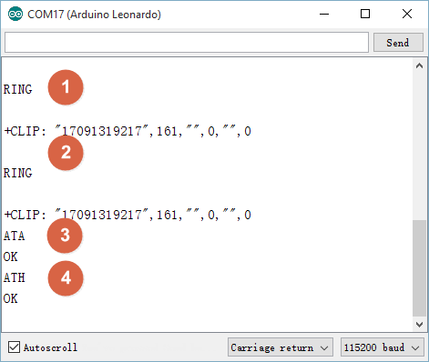
- If there is an incoming call, serial port 1 will receive the message
- The number can be displayed if your SIM card has this function
- Send ATA to answer the call
- Send ATH to reject the call
:
We recommend using DF Serial Debugger because when you are going to send the message, you have to send 0x1A in HEX. The DF Serial Debugger can send data in HEX while the Arduino IDE can't.
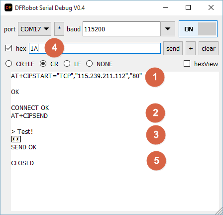
 NOTE: Do NOT tick the checkbox hex until Step 4 which is to send 0x1A in HEX.

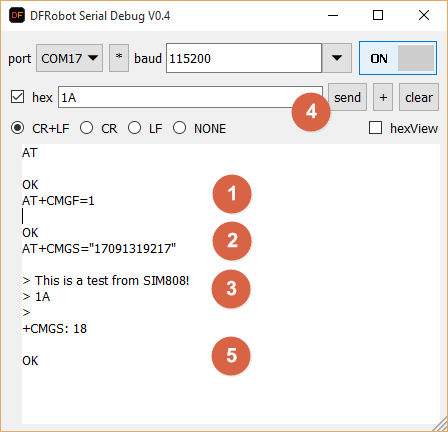
Open DF Serial Debugger and copy the settings according to the image below. If you cannot open the port, please check if the port is occupied by the Arduino IDE serial monitor.
- Send AT+CMGF=1 to set the SMS in text format. You will get OK
- Send AT+CMGS="170****9217" to set the receiver number. You will see a notation >
- Write the content of the message
- Send 1A(HEX) as an end to send the message
- You will get OK, and the message will be sent
:
- Send a message to the SIM card on the module, I sent test! here
- The serial monitor will print a message +SMTI: "SM",1, and 1 shows the number of the message
- Send AT+CMGR=1 to read the message of 1. The message "Test!" should display
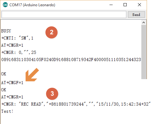
 NOTE: If the text is unreadable, please set the message in TEXT by AT+CMGF=1.
In order to do this you may first need to know how to get an available site's IP address. Follow these steps to do so:
- Press Windows+r, type cmd, click OK.
- Type a site and press Enter. e.g.www.baidu.com
- You will get some info including the IP address. e.g. 115.239.211.112
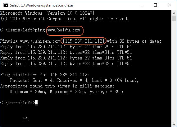
Once you are able to do this you can continue:
 NOTE: Do NOT tick the checkbox hex until Step 4 which is to send 0x1A in HEX.
- Send AT+CIPSTART="TCP","115.239.211.112","80", and you receive OK. After a while, you should see CONNECT OK. If it failed to connect, try a more common website, or powercycle the SIM808 module to reboot
- Send AT+CIPSEND to get the permission to send data to the site
- After you get a notation >, you can send your message
- Send 0x1A in HEX as an end, after a while, if the site received your data, you will see SEND OK
- After a while, the connection with the site will break off automatically if no more data is transmitted. You can also send AT+CIPCLOSE to break the connection.
:
We recommend using this feature outside for best perfomance.
- Send AT+CGNSPWR=1, the serial monitor will confirm with OK immediately
- Send AT+CGNSTST=1, the serial monitor will confirm with OK
The module should then start displaying GPS location data.
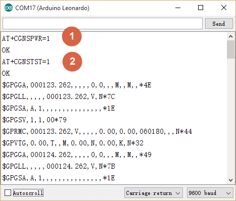
 NOTE: To get GPS position data, the module should be placed outside. Here, we did the it inside in order to demonstrate the AT commands.
Read: The raw GPS data from the serial is in the form: DDmm.mmmmm.
- e.g. If the raw information is: 5320.12345, then it is: 53 degress and 20.12345 minutes. In order to convert to decimal coordinates you need to divide the minutes by 60. i.e. 20.12345/60 = 0.33539. So the decimal result is 53.33539. Forum reading, attached source code that prints google maps friendly coordinates for SIM908 module.
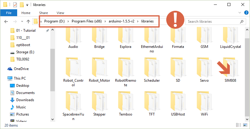 download the sim808 library and install it to arduino-1.5.*\libraries instead of Documents\Arduino\Library!
 NOTE:
NOTE:
- You have to use Arduino V1.5.*;
- The library should be placed at Arduino-1.5.*\libraries, the Arduino Installation directory.
- The SIM808 module initialization part has been completed in the library, it doesn't require the user to initialize the module
- In the debugDF.h file under the \SIM808\src folder, modifing the relevant macro definitions can print a debugging message via USB port
: open arduino v1.5.*, and you will find the sample sketch in the examples menu, upload it according to your needs, and please note that we will use Newline and a baudrate of 9600 in this section .

Steps:
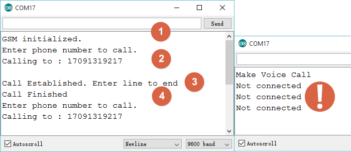
- Open the serial monitor, you will get a ready notice
- Send the number. e.g. 1709***9217. If the number is incorrect, you will receive a warning
- If the call is answered, the monitor will print text like lable 3
- If the call is rejected, the monitor will print text like lable 4
- You can send a Newline character to hang up, i.e.
- \n in code
- Do NOT type anything and click Send/ press Enter on your keyboard in serial monitor
- If you close the serial monitor and open it again, you will not see any information in the window but it will still be waiting for you to input a number to call. This is because the code runs the setup() only once.
- You can send a Newline character to hang up, i.e.
 NOTE:
NOTE:
- Make sure you have prepared everything ready to go, i.e. the NET led is flashing properly, please check the chapter above.
- The first time you open the serial monitor after uploading the sketch, the SIM808 module would reboot automatically whether the previous NET state is ON or OFF, and after about 1 minute, the Not connected message will disappear. If not, you can press BOOT button on board to BOOT it manually.
Function Explanation:
- GsmAccess.begin (): Initialize SIM808 module, some AT commands for setting is finished in this function, and it will return SIM808_READY after starting
- RemoteNumber.toCharArray (): Convert a number entered by the user into an array
- Vcs.getvoiceCallStatus (): Gets the current call status
- Vcs.hangCall (): Hangs up the call
Steps:
- Make a call to the SIM card on the module after you got the message Waiting for a call
- The module would answer the coming call automatically, and you will get the message
- You can send a Newline to hang up
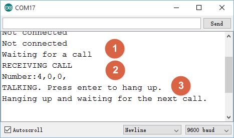
Function Explanation:
- Vcs.retrieveCallingNumber (): Get the call number
- Vcs.answerCall (): Answer the call
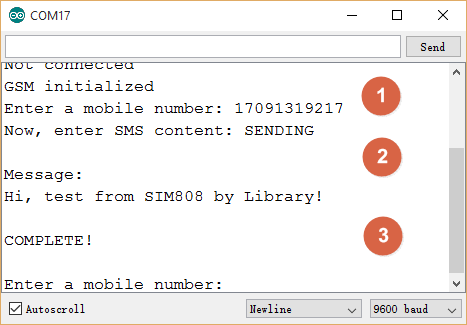
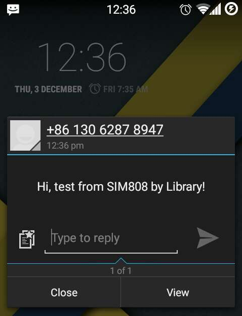 Steps:
- Send the receiver number after you see the message GSM initialized
- Send a message after you see the message Now, enter SMS...
- After a while the receiver will receive the message
Function Explanation:
- sms.beginSMS(): Send the transformed number to SIM808 module
- sms.print(): Print the message to be sent, and it will send the message into SIM808 module
- sms.endSMS(): Finish the message-delivering task
The GPS feature should be used outside, here we used it just for an explanation of the library.
Steps:
-
Find an available server and get the following settings information: (Here, we just show it as an example which doesn't work)
- char tcpip[]="\"TCP\",\"183.230.40.39\",\"876\"";
- char datastreams_id[]="GPS Data";
- char device_id[]="135506";
- char api_key[] ="Qjvc7i1UwteNzL1jOGZ8VsVJ04gA";
-
Upload the sketch and open the serial monitor, wait until the module initialization finished
-
Then it will get the state if there is any available GPS data. If it is avaible, then the data will be sent to the server
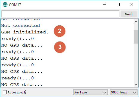
Function Explanation:
- Char Tcpip[]= "" TCP\ ", \" 183.230.40.39\ "\"876\"": This is the TCP report format, you can modify the parameters appropriately
- Mygps.availableGPS (): Check if valid GPS data is received. Sometimes you may not receive GPS data, the system will automatically filter it until it receives valid GPS data
- Mygps.readGPS (): Get the GPS data
- Mytcp.connectTCP (): Link to TCP
- Mytcp.setServerParameters (): Set user information for TCP
- Mytcp.sendTCPdata (): Send data. In the example sketch, we use it to send GPS data
- Mytcp.disConnectTCP (): Disconnect the TCP link. Of course if you want to continue sending data, you can also send it again but not disconnect the link as long as the server supports continuous transmission
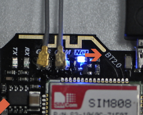
| '''Q1. '''I noticed that on the mainboard, you designed the antenna for the bluetooth2.0. But I didn't find any description about it, is it available, if so how to use it? It is very useful to me! |
'''A. ''' Welcome! It is designed for BT feature of SIM800 module as you said. However, the newest chip SIM800 is not stable when using BT, the firmware would become defective or even lost. So it is not available on this module so far. If you need use bluetooth, we suggest to buy BT module or better BLE module, Bluno is one of the popular BLE cards, you can have a look.
 Any question and more cool ideas to share, please visit DFRobot Forum
- Related Document Download all.
 shopping online from dfrobot store or dfrobot distributor.