RoMeo_BLE_(SKU_DFR0305) - jimaobian/DFRobotWiki GitHub Wiki
.jpg)
Introduction
The RoMeo BLE controller possesses all the functions of RoMeo controller, but adds one significant feature: Bluetooth 4.0 wireless communication, which allows the BLE controller to receive commands via Bluetooth. This offers the BLE a dazzling degree of customization in addition to new capabilities: users can now use their smartphone, tablet, or computer to interact with the BLE. This grants users exciting new possibilities, such as being able to fully control their mobile platforms straight from their smartphone.
Paired with Arduino, the BLE offers a dynamic range of possibilities compared to previous Arduino controllers. The RoMeo BLE is a control board specially designed for robot applications. Owing to Arduino's open-source platform and publicly available open-sourced codes, the BLE is easily integrated with Arduino modules.
The RoMeo BLE also includes two integrated two-channel DC motor drivers and wireless sockets, which provides a simpler and more convenient way for users to get their projects started.
Specifications
| '''Basic ''' | Features |
| - Microcontroller: ATmega328P |
            -   Bootloader: Arduino UNO
          -   On-board BLE chip: TI CC2540
              -   14 Digital I/O ports
- 6 PWM Outputs (Pin11, Pin10, Pin9, Pin6, Pin5, Pin3) - 8 10-bit analog input ports - 3 I2Cs - 5 Buttons - Power Supply Port: USB or DC2.1 - External Power Supply Range: 5-23V - DC output: 5V/3.3V - Size: 94mm x 80mm | - Auto sensing/switching external power input - Transmission range: 70m in free space - Support bluetooth remote update the Arduino program - Support Bluetooth HID - Support iBeacons - Support AT command to config the BLE - Support Transparent communication through Serial - Support the master-salve machine switch - Support usb update BLE chip program - Support Male and Female Pin Header - Two way H-bridgedMotor Driver with 2A maximum current - Integrated sockets for APC220 RF Module |
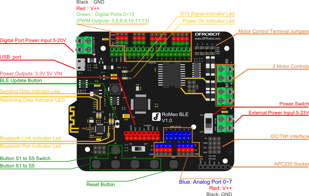
Pin Description

More detail:
- Motor Control Terminal Jumpers: Enable motor control if connected
- Button S1 to S5 Switch: Enable button functions if switched "ON"(in this case, all buttons are connected to A7).
- Motor Power Switch: Enable motor power if switched "ON"
: Cautions: Please turn OFF the Motor Power Switch, when you debug the motor with USB port.
Before you start
Applying Power
This is one of the most important steps in getting the RoMeo up and communicating with your host controller. You MUST make sure that you apply power to the Power Terminal using the correct polarity. Reverse polarity will damage the RoMeo.
Power from USB: Plug in the USB cable to the RoMeo controller from a power source (i.e. wall jack or computer). Your RoMeo should turn on -- if it does, you should notice the LED light up. Please note that the USB can only supply 500 mA current, which is enough to light up the LED but insufficient in powering DC motors or servos.
Power from External Power Input: Connect the ground wire (usually the black wire) from your supply to the screw terminal labeled “GND”, and then connect the positive wire from your supply to the screw terminal labeled “VIN".
: Cautions: Maximum supply voltage cannot exceed the voltage mentioned in Specifications.
Software
RoMeo can be programmed by Arduino IDE 0022 and above version. It can be downloaded at http://arduino.cc/en/Main/Software, Please select “Arduino UNO” as the hardware.
Romeo Configuration
Servo Power Select Jumper
Since most servos draw more power than a USB power source can supply, a separate power source is needed to individually power the servo. That separate power source is usually packaged together with the servo When you connect the external power to the servo power supply, it will automatically select the power source: either internal 5V power supply or external power source.
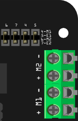
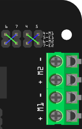
Motor Control Pin Jumper
Applying the Motor Control Pin Jumpers will allocate Pin 5,6,7,8 for motor control.
Removing the jumpers will release the above Pins.
Tutorial
New function
RoMeo BLE is an upgrade of RoMeo, based on which a new element - Bluetooth 4.0 is added. It makes RoMeo BLE continue to obtain Bluetooth 4.0 wireless communication ability after inheriting RoMeo's powerful motor drive ability. RoMeo BLE has stronger voltage and current capacity with voltage input range widened to 5-23V and current output capacity increased to 2A. Thus it can meet to more demands. Sheild interfaces are increased for I2C, IOREF and AREF, so as to compatible with more Sheild module. The buttons are replaced with comfortable and stable ones, and the jumper of buttons are also replaced with switch, making it easy to use.
Experiment
Following is small experiment that a BLE-Link communicates with RoMeo BLE through bluetooth, through which we can learn how to handle its new features - Bluetooth 4.0 wireless transmission.
-
Experimental results preview: PC sends bluetooth wireless data command through the BLE-Link to RoMeo BLE. RoMeo BLE after receiving the command switches on or off the light L according to the command.
-
Hardware preparation: a BLE-Link, a RoMeo BLE, a PC and a micro USB line.
-
Software preparation: serial debugging assistant, Arduino compiler.
-
The operation:
Step 1: Set two bluetooth devices as a master and a slave (bluetooth communication should be established between a master and a slave machine). Here we set BLE-Link as the master, while RoMeo BLE as the slave. Specifically, we first connect the BLE-Link to the PC via a USB cable and the BLE-Link would be identified as a serial port equipment. Then open the serial debugging assistant (take the V1.8 version of BLE-Link firmware to for example), send the "+++" to BLE-Link, proving that you have entered the AT command Mode when receiving "Enter into the AT command Mode". Send the BLE-Link "AT + SETTING = DEFCENTRAL" (remember to select a new line to send), meaning that the BLE-Link has been set as the master when receiving "OK". Accordingly we set the RoMeo BLE as the slave by connecting it to the PC, open the serial debugging assistant and send "+++" and "AT + SETTING = DEFPERIPHERAL".
Step 2: Arduino program on RoMeo BLE, which is used to parse the data commands to open or close the light L.
The code is as follows:
int led = 13;
char rcv_buf[10];     // Receive command arrays.
void setup()
{
  pinMode(led, OUTPUT);
  Serial.begin(115200);
}

void loop()
{
  int data_len=0;
  while(1)
  {
    while(Serial.available())
    {
       rcv_buf[(data_len++)%10] =Serial.read();
    }
    if(rcv_buf[data_len-2]== '\r' && rcv_buf[data_len-1]=='\n')      // Stop reading the serial once getting the ending command.
       break;
  }
  if ((data_len==4)&&(!strncmp(rcv_buf,"ON",2)))      // Open the light L when the command is "ON".
  {
       digitalWrite(led, HIGH);                       // Set D13 pin as high and openg the light L
       Serial.println("LIHGT ON");
  }else if((data_len==5)&&(!strncmp(rcv_buf,"OFF",3)))   // Close the light L when the command is "OFF".
  {
       digitalWrite(led, LOW);                      // Set D13 pin as low and  the light L
       Serial.println("LIHGT OFF");
  }
}
Step 3: Connect the BLE-Link to the PC, and meanwhile open the RoMeo BLE. Wait a few seconds the two bluetooth devices will automatically connect. The LINK light will be on showing connection, indicating that the two devices are ready for wireless communication. Then open the serial debugging assistant and send "ON" under the mode of New line. This command is sent from the serial port, passing through the BLE-Link to RoMeo BLE. RoMeo BLE after receiving the command will parse the Arduino program, and then open the light L. When sending OFF under the mode of New line, RoMeo BLE turns OFF the light L.
Buttons
RoMeo BLE integrated 5 buttons, S1 to S5, which are controlled by Anolog Port 7. Switch it on as shown in the following figure when using analog buttons.
Demo Code 1:
int potPin = 7;
int ledPin = 13;
int val = 0;

void setup() {
  pinMode(ledPin, OUTPUT);
}

void loop() {
  val = analogRead(potPin);
  digitalWrite(ledPin, HIGH);  // Open the LED.
  delay(val);
  digitalWrite(ledPin, LOW);   // Close the LED.
  delay(val);
}
Program function: Press buttons of S1 to S2, different frequencies of the LED flashing will be seen. This is because different resistances are built in, leading to different voltage dispatched to the analog ports. So do the data acquired by AD.
Demo Code 2:
int adc_key_val[5] ={50, 200, 400, 600, 800 };
int NUM_KEYS = 5;
int adc_key_in;
int key=-1;
int oldkey=-1;

void setup(){
  pinMode(13, OUTPUT);  //LED13 is used for mesure the button state.
  Serial.begin(115200);
}

void loop(){
  adc_key_in = analogRead(7);
  digitalWrite(13,LOW);
  key = get_key(adc_key_in);  //Call the button judging function.

  if (key != oldkey){   // Get the button pressed
      delay(50);
      adc_key_in = analogRead(7);
      key = get_key(adc_key_in);
      if (key != oldkey)    {
        oldkey = key;
        if (key >=0){
          digitalWrite(13,HIGH);
          switch(key){          // Send messages accordingly.
             case 0:Serial.println("S1 OK");
                    break;
             case 1:Serial.println("S2 OK");
                    break;
             case 2:Serial.println("S3 OK");
                    break;
             case 3:Serial.println("S4 OK");
                    break;
             case 4:Serial.println("S5 OK");
                    break;
          }
        }
      }
  }
  delay(100);
}

// To know the pressed button.
int get_key(unsigned int input){
    int k;
    for (k = 0; k < NUM_KEYS; k++){
      if (input < adc_key_val[k]){     // Get the button pressed
            return k;
      }
   }
   if (k >= NUM_KEYS)k = -1;  // No button is pressed.
   return k;
}
Program function: See what happens in the serial window when pressing buttons, S1 to S5.
Example use of Button S1-S5:
char msgs[5][15] = {
  "Right Key OK ",
  "Up Key OK    ",
  "Down Key OK  ",
  "Left Key OK  ",
  "Select Key OK" };
char start_msg[15] = {
  "Start loop "};
int  adc_key_val[5] ={
  30, 150, 360, 535, 760 };
int NUM_KEYS = 5;
int adc_key_in;
int key=-1;
int oldkey=-1;
void setup() {
  pinMode(13, OUTPUT);  //we'll use the debug LED to output a heartbeat
  Serial.begin(115200);

  /* Print that we made it here */
  Serial.println(start_msg);
}

void loop()
{
  adc_key_in = analogRead(7);    // read the value from the sensor
  digitalWrite(13, HIGH);
  /* get the key */
  key = get_key(adc_key_in);    // convert into key press
  if (key != oldkey) {   // if keypress is detected
    delay(50);      // wait for debounce time
    adc_key_in = analogRead(7);    // read the value from the sensor
    key = get_key(adc_key_in);    // convert into key press
    if (key != oldkey) {
      oldkey = key;
      if (key >=0){
        Serial.println(adc_key_in, DEC);
        Serial.println(msgs[key]);
      }
    }
  }
  digitalWrite(13, LOW);
}
// Convert ADC value to key number
int get_key(unsigned int input)
{
  int k;
  for (k = 0; k < NUM_KEYS; k++)
  {
    if (input < adc_key_val[k])
    {
      return k;
    }
  }
  if (k >= NUM_KEYS)
    k = -1;     // No valid key pressed
  return k;
}
Speed regulation of the two-armature DC motor
RoMeo BLE used 2 motor drivers so as to save time for robot fans spent on making hardware and to focus on software development. Using L298 motor drive circuit, the peak current can be up to 2A. When using the motor drive, the problem of power supply will be up. As shown in the figure below, M_VIN is connected to the anode, and GND is connected to the cathode. Also remember to switch to "ON".
PWM control mode
|
 | | | |
|:---------:|:-------------------------:|
| Pin | Function |
| Digital 4 | Motor 1 Direction control |
| Digital 5 | Motor 1 PWM control |
| Digital 6 | Motor 2 PWM control |
| Digital 7 | Motor 2 Direction control | |
The motor driver circuit control terminal uses a short-jumper to set on or off. Set on when connected and off when disconnected.
Sample Code:
//Standard PWM DC control
int E1 = 5;     //M1 Speed Control
int E2 = 6;     //M2 Speed Control
int M1 = 4;    //M1 Direction Control
int M2 = 7;    //M1 Direction Control

///For previous Romeo, please use these pins.
//int E1 = 6;     //M1 Speed Control
//int E2 = 9;     //M2 Speed Control
//int M1 = 7;    //M1 Direction Control
//int M2 = 8;    //M1 Direction Control


void stop(void)                    //Stop
{
  digitalWrite(E1,LOW);
  digitalWrite(E2,LOW);
}
void advance(char a,char b)          //Move forward
{
  analogWrite (E1,a);      //PWM Speed Control
  digitalWrite(M1,HIGH);
  analogWrite (E2,b);
  digitalWrite(M2,HIGH);
}
void back_off (char a,char b)          //Move backward
{
  analogWrite (E1,a);
  digitalWrite(M1,LOW);
  analogWrite (E2,b);
  digitalWrite(M2,LOW);
}
void turn_L (char a,char b)             //Turn Left
{
  analogWrite (E1,a);
  digitalWrite(M1,LOW);
  analogWrite (E2,b);
  digitalWrite(M2,HIGH);
}
void turn_R (char a,char b)             //Turn Right
{
  analogWrite (E1,a);
  digitalWrite(M1,HIGH);
  analogWrite (E2,b);
  digitalWrite(M2,LOW);
}
void setup(void)
{
  int i;
  for(i=4;i<=7;i++)
    pinMode(i, OUTPUT);
  Serial.begin(115200);      //Set Baud Rate
  Serial.println("Run keyboard control");
}
void loop(void)
{
  if(Serial.available()){
    char val = Serial.read();
    if(val != -1)
    {
      switch(val)
      {
      case 'w'://Move Forward
        advance (255,255);   //move forward in max speed
        break;
      case 's'://Move Backward
        back_off (255,255);   //move back in max speed
        break;
      case 'a'://Turn Left
        turn_L (100,100);
        break;
      case 'd'://Turn Right
        turn_R (100,100);
        break;
      case 'z':
        Serial.println("Hello");
        break;
      case 'x':
        stop();
        break;
      }
    }
    else stop();
  }
}
PLL Control Mode
The Romeo also supports PLLPhase locked loop control mode.
|
 | | | |
|:---------:|:-------------------------:|
| Pin | Function |
| Digital 4 | Motor 1 Enable control |
| Digital 5 | Motor 1 Direction control |
| Digital 6 | Motor 2 Direction control |
| Digital 7 | Motor 2 Enable control | |
Sample Code:
//Standard DLL Speed control

int E1 = 4;     //M1 Speed Control
int E2 = 7;     //M2 Speed Control
int M1 = 5;    //M1 Direction Control
int M2 = 6;    //M1 Direction Control

///For previous Romeo, please use these pins.
//int E1 = 6;     //M1 Speed Control
//int E2 = 9;     //M2 Speed Control
//int M1 = 7;    //M1 Direction Control
//int M2 = 8;    //M1 Direction Control

//When m1p/m2p is 127, it stops the motor
//when m1p/m2p is 255, it gives the maximum speed for one direction
//When m1p/m2p is 0, it gives the maximum speed for reverse direction

void DriveMotorP(byte m1p, byte m2p){    //Drive Motor Power Mode

  digitalWrite(E1, HIGH);
  analogWrite(M1, (m1p));

  digitalWrite(E2, HIGH);
  analogWrite(M2, (m2p));

}

void setup(void) {
  int i;
  for(i=4;i<=7;i++)
    pinMode(i, OUTPUT);
  Serial.begin(115200);      //Set Baud Rate
}

void loop(void) {
  if(Serial.available()){
    char val = Serial.read();
    if(val!=-1){
      switch(val){
      case 'w'://Move Forward
        DriveMotorP(0xff,0xff); // Max speed
        break;
      case 'x'://Move Backward
        DriveMotorP(0x00,0x00);
        ; // Max speed
        break;
      case 's'://Stop
        DriveMotorP(0x7f,0x7f);
        break;
      }
    }
  }
}
Program function: Input "w", "x" and "s" and the motor will act accordingly.
The serial port using
RoMeo BLE uses the same serial ports as RoMeo other than adding a serial for Bluetooth 4.0 transparent communication. Related commands can be refered to the functions, Serial.begin(), Serial.read(), Serial.print() and Serial.println(),provided by Arduino.
Sample for RoMeo BLE connecting to smart phones
Please refer to Sample for Bluno connecting to smart phones
Step by Step Basic Demo tutorial.
Wireless programming via BLE
Please refer to Wireless programming via BLE of Bluno
How to Wireless Programming through BLE.
Forum page about BLE LINK Wireless Programming
Configurate the BLE part using AT commands
Please refer to BLE configuration using AT commands of Bluno
BLE firmware update of Bluno mega2560 ("AT + VERSION" to check the version)
Please refer to BLE firmware update of Bluno
How to update the BLE firmware.
More
- Old Version:Romeo V2-All in one Controller
- 3D module (Share by Jared Peters) Clink Here
 buy from dfrobot store or dfrobot distributor list