Relay_Shield_for_Arduino_(SKU_DFR0144) - jimaobian/DFRobotWiki GitHub Wiki

Introduction
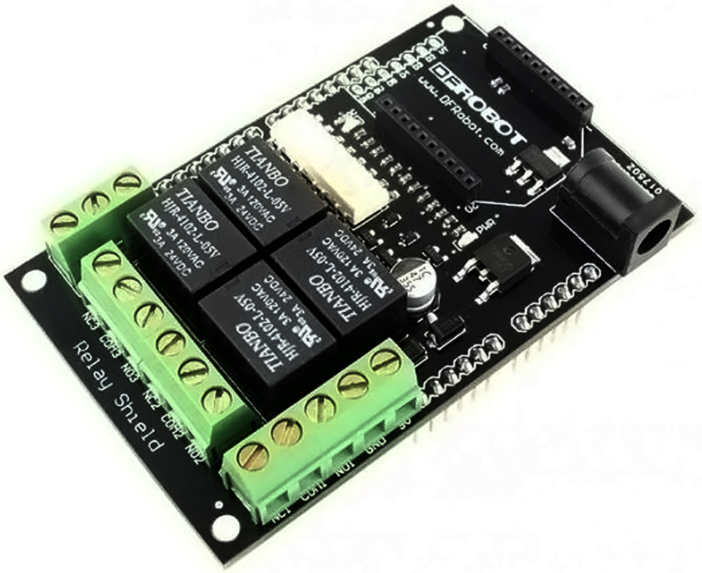
The DFRobot Relay shield is capable of controlling 4 relays. The max switching power is DC 90W or AC 360VA. It is possible to control the Relay shield through Arduino/DFRduino using digital IOs with external 9v supply. With the built in xbee socket, it can be wirelessly controlled via Xbee/bluetooth/WPM. This makes it an ideal solution for automation and robotics.
Specifications
# Up to 4 Relay with photo-coupled circuit
- Contact Rating 3A AC 120V / DC 24V
- Max Switching Voltage AC 240V / DC 60V
- Max Switching Current 5A
- Max Switching Power AC 360VA / DC 90W
- Electrical Life (Min) 100,000 Operations
- Mechanical Life (Min) 10,000,000 Operations
- Safety Standard(relay) UL cUL TUV CQC
- Coil Working Voltage 9VDC
- Weight 165g
- Working temperature -30℃ to +85℃
- Working temperature 40% - 85%
Relay Shield Schematic Relay Data Sheet
Technical Information
Pin Mapping D2 -> COM1 D3 -> COM2 D4 -> COM3 D5 -> COM4 NC Normally Closed - NC1 is connected with COM1 when control port D2 is set low and disconnected when D2 is set high NO Normally Open - NO1 is disconnected from COM1 when control port D2 is set low and connected when D2 is set high 9v power supply connection The function of the Terminal and the Jack is the same since they are internally connected, and you can choose either of them as needed. You can also supply power from the Arduino power jack. XBee interface The XBee module supports Xbee radios, Bluetooth Bee, and the Wireless programming module. This gives the project a versatile wireless communications capability.
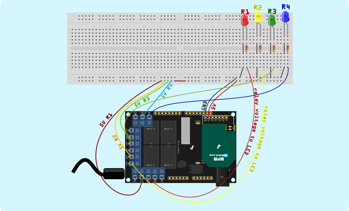
Connection Diagram
In this sample connection diagram it shows how some LEDs can be controlled via relays, while this is a bit of overkill for controlling LEDs its only meant to be an example. These relays can be used to control lamps, or some other mid-voltage range appliances.

Sample Code
byte relayPin[4] = {2,3,4,5};

//D2 -> RELAY1
//D3 -> RELAY2
//D4 -> RELAY3
//D5 -> RELAY4

void setup(){
  for(int i = 0; i < 4; i++)  pinMode(relayPin[i],OUTPUT);
}

// an sample to switch the 4 relays

void loop(){

  int i;
  for(i = 0; i < 4; i++)  digitalWrite(relayPin[i],HIGH);
  delay(1000);
  for(i = 0; i < 4; i++)  digitalWrite(relayPin[i],LOW);
  delay(1000);

}
A more elaborate sample code
char input= 0;
int x;
void setup() {
  DDRD =B11111110;
 Serial.begin(57600);
  delay(100);
 Serial.println();
 Serial.println("Relay shield sample code");
 Serial.println("Press 1-4 to control the state of the relay");
 Serial.println("This sample will cycle each of the relays once, then wait for your input");


  PORTD=B00000100; //address for Relay 1 (Digital pin 2)
  delay(250);
  PORTD=B00001100; //address for Relay 2 (Digital pin 3)
  delay(250);
  PORTD=B00011100; //address for Relay 3 (Digital pin 4)
  delay(250);
  PORTD=B00111100; //address for Relay 4 (Digital pin 5)
  delay(250);
  PORTD=B00000000; //Set all relays to off position.
  delay(250);

 Serial.println("waiting for input:");
}

void loop() {

  if (Serial.available() > 0) {
    input= Serial.read();
    Serial.print("toggle: ");


    if(input =='1'){
      Serial.println("Relay 1");
      x=(bitRead(PORTD,2));
      x=!x;
      bitWrite(PORTD,2,x);

    }else if (input =='2'){
       Serial.println("Relay 2");
       x=(bitRead(PORTD,3));
       x=!x;
       bitWrite(PORTD,3,x);

    }else if (input =='3'){
       Serial.println("Relay 3");
       x=(bitRead(PORTD,4));
       x=!x;
       bitWrite(PORTD,4,x);

    }else if (input =='4'){
       Serial.println("Relay 4");
       x=(bitRead(PORTD,5));
       x=!x;
       bitWrite(PORTD,5,x);

    } else{
      Serial.print(input);
      Serial.println("  Is an invalid entry, please press 1,2,3, or 4");
    }
}
}
Additional Documentation
RAR File with Sample code, schematics, and data sheet

shopping relay shield
category: Product Manual category: DFR Series category: Shields category: source category: Diagram