Real_Time_Clock_Module_(DS1307)_(SKU_DFR0151) - jimaobian/DFRobotWiki GitHub Wiki

This is the DS1307 Real Time Clock developed by one of our designer waiman. The module comes fully assembled and pre-programmed with the current time (ok, so it's our current time - MST). The included Lithium coin cell battery (CR1225 41mAh) will run the module for a minimum of 9 years (17 years typical) without external 5V power. The DS1307 is accessed via the I2C protocol.
- Two wire I2C interface
- Hour : Minutes : Seconds AM/PM
- Day Month, Date - Year
- Leap year compensation
- Accurate calendar up to year 2100
- Battery backup included
- 1Hz output pin
- 56 Bytes of Non-volatile memory available to user

// #############################################################################
// #
// # Scriptname : DS1307_Test.pde
// # Author     : Peter Schmelzer, Oliver Kraus
// # Date       : 2011-04-08

// # Editor     : Lauren from DFRobot
// # Date       : 30.12.2011

// # Description:
// # Test file for the DS1307new library. Assumes that you have a DS1307
// # connected to the I2C-Bus of your Arduino and that it has a battery backup.
// # Update the library and sketch to compatible with IDE V1.0 and earlier

// # Version    : 1.0
// #############################################################################
// *********************************************
// INCLUDE
// *********************************************
#include <Wire.h>                       // For some strange reasons, Wire.h must be included here
#include <DS1307new.h>

// *********************************************
// DEFINE
// *********************************************

// *********************************************
// VARIABLES
// *********************************************
uint16_t startAddr = 0x0000;            // Start address to store in the NV-RAM
uint16_t lastAddr;                      // new address for storing in NV-RAM
uint16_t TimeIsSet = 0xaa55;            // Helper that time must not set again

// *********************************************
// SETUP
// *********************************************
void setup()
{
  pinMode(2, INPUT);                    // Test of the SQW pin, D2 = INPUT
  digitalWrite(2, HIGH);                // Test of the SQW pin, D2 = Pullup on

  Serial.begin(9600);

/*
   PLEASE NOTICE: WE HAVE MADE AN ADDRESS SHIFT FOR THE NV-RAM!!!
                  NV-RAM ADDRESS 0x08 HAS TO ADDRESSED WITH ADDRESS 0x00=0
                  TO AVOID OVERWRITING THE CLOCK REGISTERS IN CASE OF
                  ERRORS IN YOUR CODE. SO THE LAST ADDRESS IS 0x38=56!
*/
  RTC.setRAM(0, (uint8_t *)&startAddr, sizeof(uint16_t));// Store startAddr in NV-RAM address 0x08

/*
   Uncomment the next 2 lines if you want to SET the clock
   Comment them out if the clock is set.
   DON'T ASK ME WHY: YOU MUST UPLOAD THE CODE TWICE TO LET HIM WORK
   AFTER SETTING THE CLOCK ONCE.
*/
//  TimeIsSet = 0xffff;
//  RTC.setRAM(54, (uint8_t *)&TimeIsSet, sizeof(uint16_t));

/*
  Control the clock.
  Clock will only be set if NV-RAM Address does not contain 0xaa.
  DS1307 should have a battery backup.
*/
  RTC.getRAM(54, (uint8_t *)&TimeIsSet, sizeof(uint16_t));
  if (TimeIsSet != 0xaa55)
  {
    RTC.stopClock();

    RTC.fillByYMD(2011,4,8);
    RTC.fillByHMS(22,7,0);

    RTC.setTime();
    TimeIsSet = 0xaa55;
    RTC.setRAM(54, (uint8_t *)&TimeIsSet, sizeof(uint16_t));
    RTC.startClock();
  }
  else
  {
    RTC.getTime();
  }

/*
   Control Register for SQW pin which can be used as an interrupt.
*/
  RTC.ctrl = 0x00;                      // 0x00=disable SQW pin, 0x10=1Hz,
                                        // 0x11=4096Hz, 0x12=8192Hz, 0x13=32768Hz
  RTC.setCTRL();

  Serial.println("DS1307 Testsketch");
  Serial.println("Format is \"hh:mm:ss dd-mm-yyyy DDD\"");

  uint8_t MESZ;

  MESZ = RTC.isMEZSummerTime();
  Serial.print("MEZ=0, MESZ=1 : ");
  Serial.println(MESZ, DEC);
  Serial.println();
}

// *********************************************
// MAIN (LOOP)
// *********************************************
void loop()
{
  RTC.getTime();
  if (RTC.hour < 10)                    // correct hour if necessary
  {
    Serial.print("0");
    Serial.print(RTC.hour, DEC);
  }
  else
  {
    Serial.print(RTC.hour, DEC);
  }
  Serial.print(":");
  if (RTC.minute < 10)                  // correct minute if necessary
  {
    Serial.print("0");
    Serial.print(RTC.minute, DEC);
  }
  else
  {
    Serial.print(RTC.minute, DEC);
  }
  Serial.print(":");
  if (RTC.second < 10)                  // correct second if necessary
  {
    Serial.print("0");
    Serial.print(RTC.second, DEC);
  }
  else
  {
    Serial.print(RTC.second, DEC);
  }
  Serial.print(" ");
  if (RTC.day < 10)                    // correct date if necessary
  {
    Serial.print("0");
    Serial.print(RTC.day, DEC);
  }
  else
  {
    Serial.print(RTC.day, DEC);
  }
  Serial.print("-");
  if (RTC.month < 10)                   // correct month if necessary
  {
    Serial.print("0");
    Serial.print(RTC.month, DEC);
  }
  else
  {
    Serial.print(RTC.month, DEC);
  }
  Serial.print("-");
  Serial.print(RTC.year, DEC);          // Year need not to be changed
  Serial.print(" ");
  switch (RTC.dow)                      // Friendly printout the weekday
  {
    case 1:
      Serial.print("MON");
      break;
    case 2:
      Serial.print("TUE");
      break;
    case 3:
      Serial.print("WED");
      break;
    case 4:
      Serial.print("THU");
      break;
    case 5:
      Serial.print("FRI");
      break;
    case 6:
      Serial.print("SAT");
      break;
    case 7:
      Serial.print("SUN");
      break;
  }
  Serial.print(" seconds since 1.1.2000:");
  Serial.print(RTC.time2000, DEC);
  uint8_t MESZ = RTC.isMEZSummerTime();
  Serial.print(" MEZ=0, MESZ=1 : ");
  Serial.print(MESZ, DEC);

  Serial.print(" - Address in NV-RAM is: ");
  RTC.getRAM(0, (uint8_t *)&lastAddr, sizeof(uint16_t));
  Serial.print(lastAddr, HEX);
  lastAddr = lastAddr + 1;              // we want to use it as addresscounter for example
  RTC.setRAM(0, (uint8_t *)&lastAddr, sizeof(uint16_t));
  RTC.getRAM(54, (uint8_t *)&TimeIsSet, sizeof(uint16_t));
  if (TimeIsSet == 0xaa55)              // check if the clock was set or not
  {
    Serial.println(" - Clock was set!");
  }
  else
  {
    Serial.println(" - Clock was NOT set!");
  }
  delay(1000);                          // wait a second
}Arduino Library (compatible with IDE version 1.0 and lower)
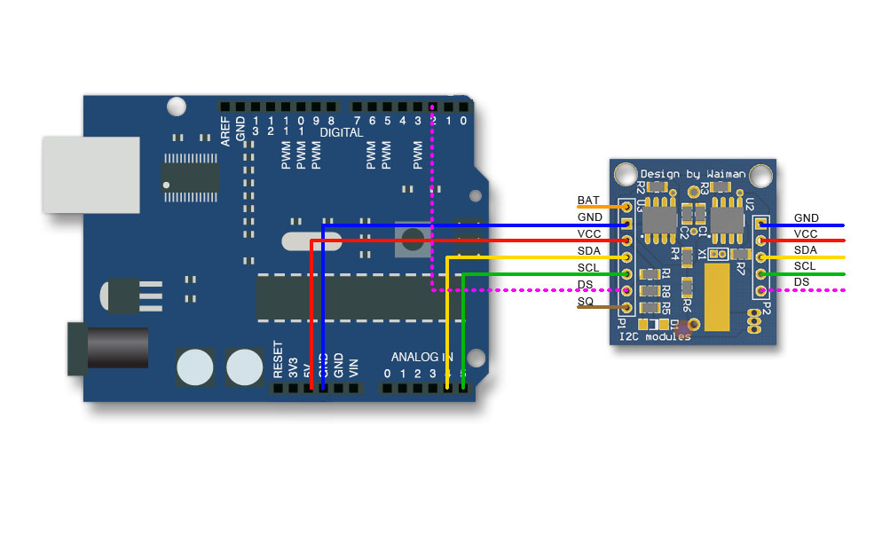
Sample code, library, and wiring diagram
 shopping real time clock module (ds1307) (sku:dfr0151)
category: Product Manual category: DFR Series category: Modules category: source category: Diagram