RLY 8 RS485_8_Relay_Controller_SKU_DFR0290 - jimaobian/DFRobotWiki GitHub Wiki
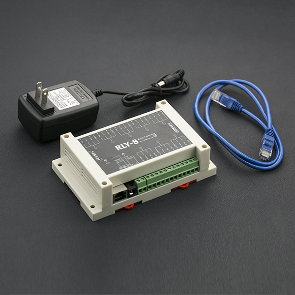
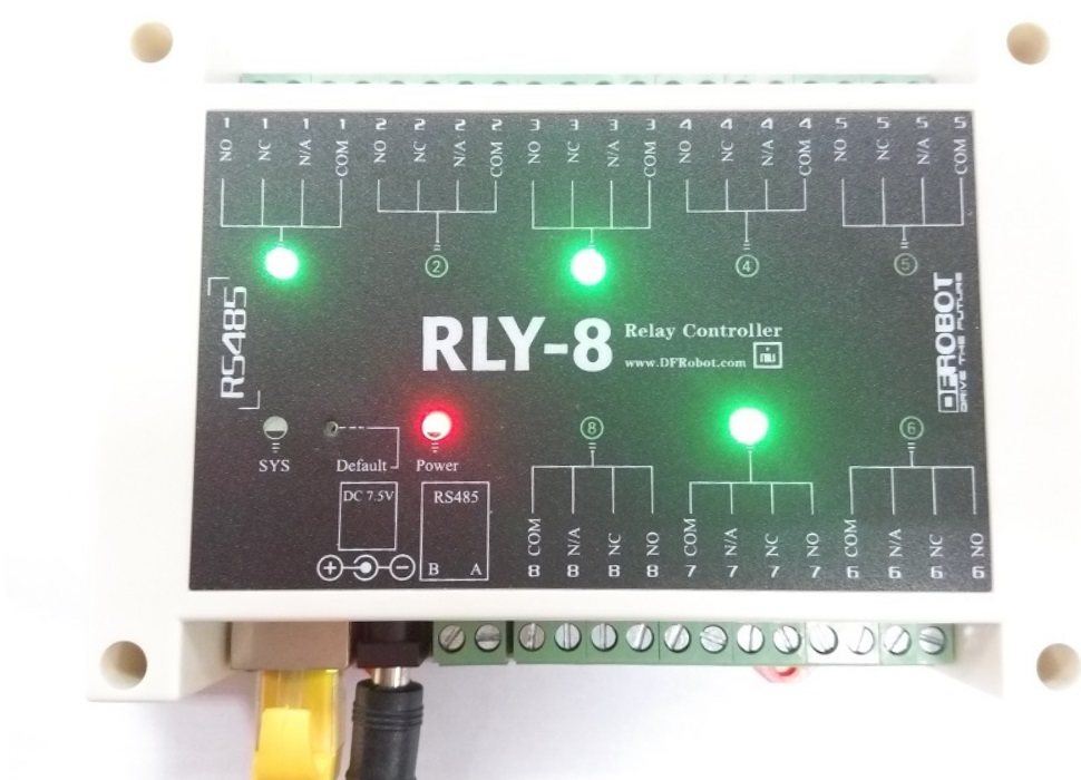
The RLY-8 is a network relay controller with open source communication protocol. It integrates 8 channel relays and each relay could stand 277VAC-10A or 125VAC-12A power. Meanwhile most of the household appliances are under 250VAC, it means you could use it almost everywhere. The RLY-8 is using STM32 microcontroller. It supports 2 types of power supply: Wall adapter or PoE (Power over Ethernet) power supply. You could reduce its connection cable via PoE power supply. In addition, you also could control it via RS485 port or TCP/IP protocol. And RS485 and JSON protocol has been opened on the website. This Ethernet relays are really great for IoT projects - with 8 relays, you have plenty of scope to try different things. Like a remote control light, a autoflowering greenhouse. With the open source protocol, you could add it in plenty of things you can do with this besides, just use your imagination!
- Operating Voltage: DC:7-23V
- Relay number: 8
- Data Communication: Ethernet/RS485
- Network Configuration: Supports DHCP and Static IP
- Power Consumption: Max 3.5W
- Maximum Control: 277VAC-10A/125VAC-12A
- Control Mode: Ethernet/RS485
- Factory Settings: IP: 192.168.1.10 (port: 2000)
- Working Temperature: -30~85℃
- Weight: 530g
- Size: 145mm * 90mm * 40mm (5.7in * 3.5in * 1.6in)
-
Hardware
- POE relay x1
- PC X1
- USB to RS485 transfer line or ethernet cable
- POE Ethernet switch or ordinary Ethernet switch
-
Software
- PC Software (Windows) Click to Download
RLY-8-PoE-RS485 supports 2 types of control mode: Ethernet and RS485 In this section, we will introduce some typical connection:
- Ethernet
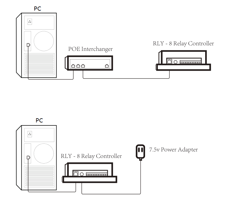
| NOTE: If you directly connect to the computer, you will need to set a static IP. Going by RLY factory settings, you can set your computer IP to 192.168.1.x(x is 0~254 except 10), Subnetmask 255.255.255.0, gateway 192.168.1.1 |
- RS485 BUS
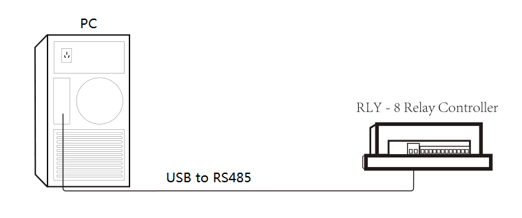
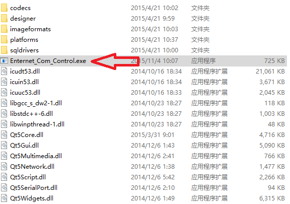
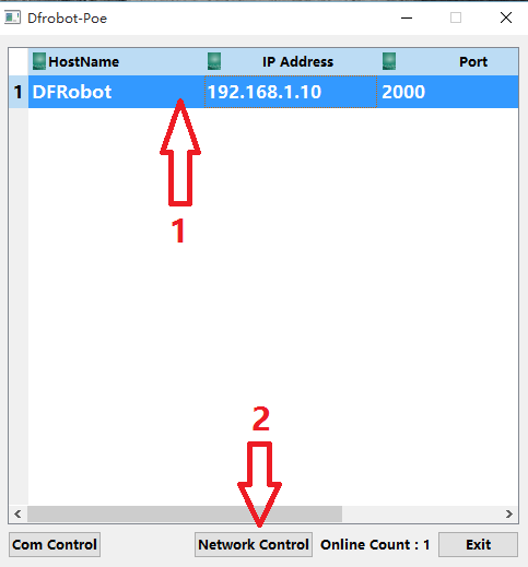
| NOTE: It may take some time when the RLY-8 has just been powered on, please be patient waiting for the network list |
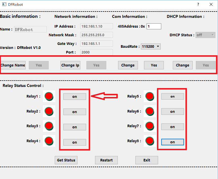
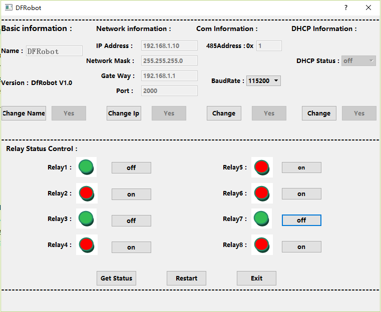
| NOTE: It is recommended to click the "Get Status" button to get the current state when you want to control the relay. |
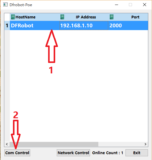
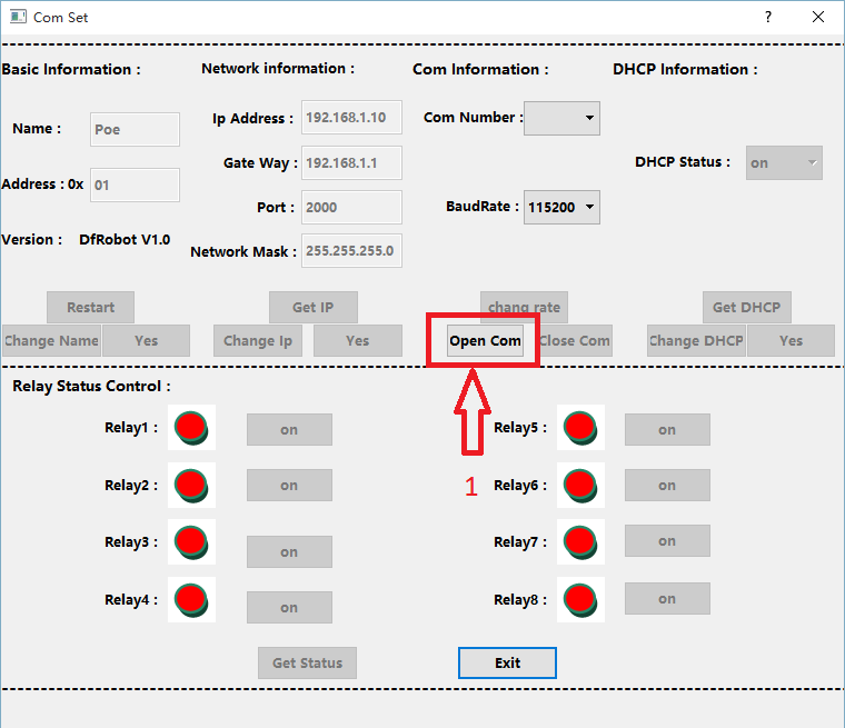
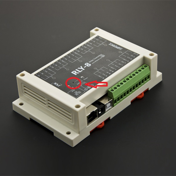
To reset the factory default settings, hold the reset button until the lights begin to flash.
| '''Q1. '''Some general Arduino Problems/ FAQ/ Tips, very good to know. |
'''A. '''Clike the topic link on DFRobot Forum.
| '''Q2. '''The RELY-8-POE-EN.pdf document (below) describes using JSON messages to set and get relay states. I am trying to get this to work but I am unsure how. Is there sample code? |
'''A. '''This open source protocal is for advanced JSON users, if you know JSON well, you could use the JSON command by connecting the Relay Controller to TCP port2000. If not, here is an official introduce about JSON, and you could google more tutorial about JSON if you want to develope your own software to use this relay controller. BTW, we have passed test on Telnet (PuTTY) and TCP/IP Net Assistant, clike to download TCP/IP Net Assistant.
 For any questions/advice/cool ideas to share, please visit DFRobot Forum.
 shop online at the dfrobot store or dfrobot distributor.