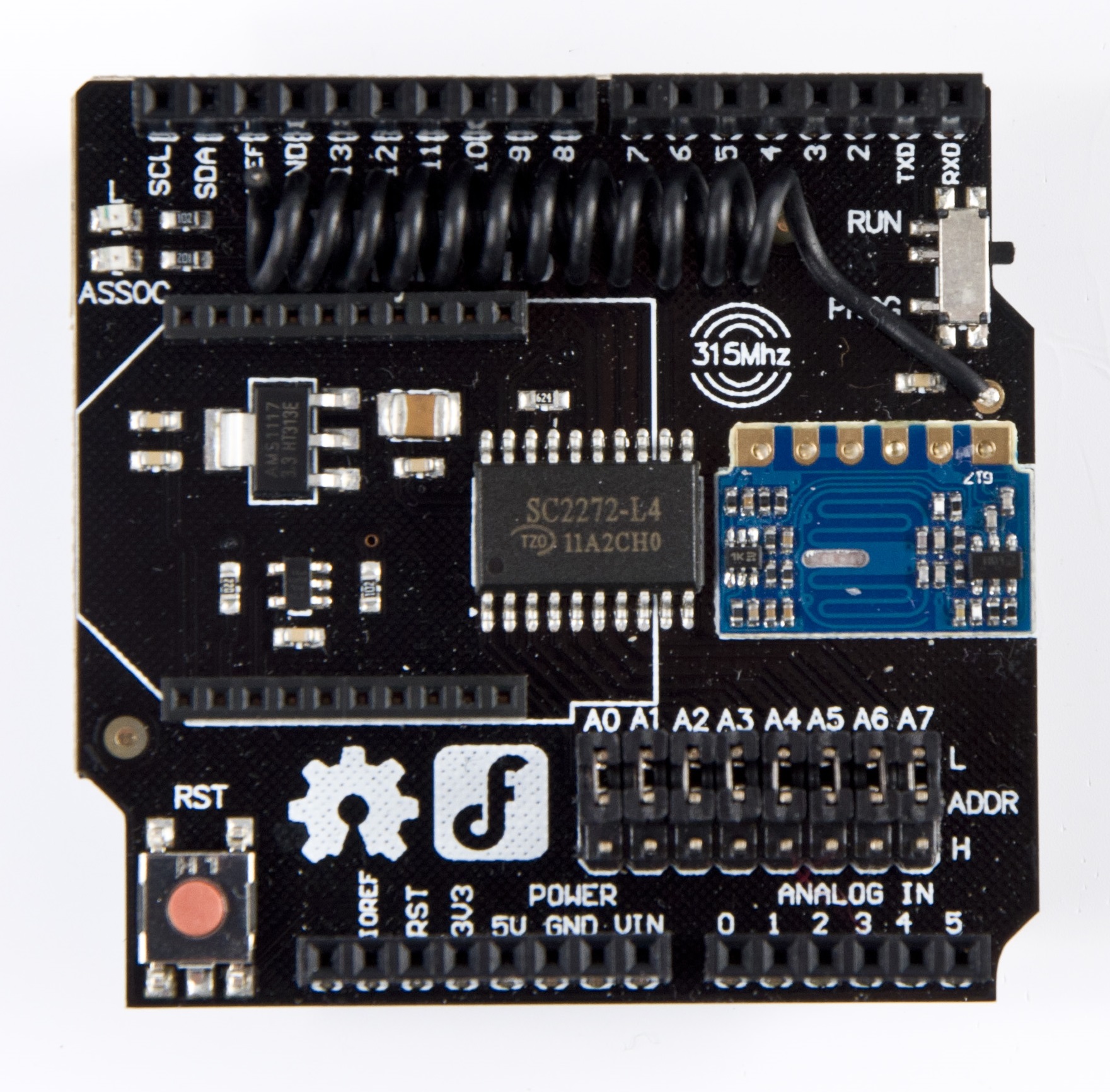
RF_Shield(315MHz)(SKU_TEL0075) - jimaobian/DFRobotWiki GitHub Wiki

Introduction
- The 315M wireless module is widely used in vehicle monitoring, remote control, home security system, wireless meter reading, guard monitor system, industrial data acquisition system, wireless tag, identification, non-contact RF card, small wireless data terminals, fire safety systems, wireless remote control system, biological signal acquisition, hydrological and meteorological monitoring, robot control and so on.
- The 315MHz RF receiving module launched by DFRobot can be easily integrated into the existing 315M wireless network.At the same time, a XBee interface is integrated on this module, so it provide makers more wireless solutions,such as 315M to Bluetooth, 315M to WiFi, 315M to Xbee.
- This RF Shield can communicate with the 315M sensors or controllers which use SC2260, SC2262, PT2260, PT2262 encoding chip as the core.
Application
- The 315M wireless communication, such as wireless remote control, small wireless data terminal, home security system, and so on.
Specification
- Module Interface: Arduino Compatible
- Occupied Pin: Digital Pin 3,8,9,10,11
- Operating Frequency: 315MHz
- Operating Current: 10mA(Maximum)
- Modulation Mode: ASK
- Demodulation Mode: Super Heterodyne Demodulation
- Sensitivity: -102dBm(Typical),-98dBm(Worst)
- Transmission Rate: 9.6kbps(Maximum)
- Receiving Bandwidth: ±1.25MHz(6dB)
- Antenna Impedance: 75Ω
- Decoder Chip: SC2272(Latch)
- Data Output: Compatible with CMOS Level Standard
- Expansion Interface: XBee Interface
- Transmission distance: <40M(Open Spaces)
- Operating Temperature: 0℃ to 70 ℃
Set Address Code
The RF Shield has 8 three-state address pins, which can support up to 6561 address code.The three state is High,Low and Floating.The level of the pin is set by the jumper.Above the address pin,there is L.Under the address pin,there is H. So,if you jump the L and the address pin,the level of the address pin is Low.In like manner,if jump to H,the level is High. Remove the jumper,the level is Floating. In actual use, address code depends on the remote control. Only the address codes are equal, it is possible to carry out communication. Our remote wireless keynob 315MHz(SKU:FIT0355) default address code is floating, therefore,you must remove all the jumpers. You can also disassemble the remote control, set the short leg to modify the remote address code.
Use the RF Shield
- SC2272 is used as the receiving and decoding chip on the RF Shield, and it is generally used with SC2262. Other compatible models can also be used. RF Shield has 8 three-state address pins, which can support up to 6561 address code. This greatly reduces the coding conflict and illegal for code scanning to the possibility of matching.
- In order to ensure that SC2272 can reliably receive data sent by SC2262, the SC2272 oscillation frequency should match the frequency of SC2262 oscillation. The best matching oscillation frequency is that SC2272 is 2 times of SC2262. Oscillation frequency can be changed by adjusting the oscillation resistance. When purchasing the emission supporting device and RF Shield, you need to pay attention to the firing frequency, transmitter chip model and vibration resistance is optional.
- Here are a few compatible transmitting chip oscillation resistance model matching parameters:
| Chip Model | SC2272(RF Shield) | Transmitter | SC2262 | SC2260 | PT2260 | PT2262 |
| Oscillation Resistance Value | 620K(Default Values) | Matching Resistor Values | 4.7M | 12M | 1.2M | 4.7M |
We recommand you to use our remote wireless keynob 315MHz(SKU:FIT0355).It is simple and convenient!
# According to the address code of the remote wireless telecontroller, set the address code of this shield by pluging or pulling the jumper.Only when the address code of the telecontroller is equal to the address code of the shield, the command transmit by the telecontroller can be received by this shield. The address code of our remote wireless keynob 315MHz(SKU:FIT0355) is floating, so you must remove all the jumpers.(8 jumpers all) # Turn the switch to PROG,upload the sample code to your Arduino. When done, turn the switch to RUN. # Adjust the position of the antenna, which makes it perpendicular to the board. This can increase the receiving distance. # Open the serial monitor, press the button on the telecontroller.You can see the LED will twinkle once when you press the button. This indicates that this shield has received command from the telecontroller. You can also see which button pressed on the serial monitor. The high level 1 is the pressed button.
Sample Code
/*The following 4 pin definitions,correspond to 4 buttons on the remote control(The telecontroller is Remote Wireless Keynob 315MHz(SKU:FIT0355))*/
int D1 = 8;    //The digital output pin 1 of decoder chip(SC2272)
int D2 = 9;    //The digital output pin 2 of decoder chip(SC2272)
int D3 = 10;   //The digital output pin 3 of decoder chip(SC2272)
int D4 = 11;   //The digital output pin 4 of decoder chip(SC2272)
int ledPin = 13;   //Receiving indicator

volatile int state = LOW;

void setup()
{
  Serial.begin(9600);
  /*The four pins order below correspond to the 4 buttons on the remote control.*/
  pinMode(D4, INPUT);  //Initialized to input pin, in order to read the level of the output pins from the decoding chip
  pinMode(D2, INPUT);
  pinMode(D1, INPUT);
  pinMode(D3, INPUT);
  pinMode(ledPin, OUTPUT);
  attachInterrupt(1,blink,RISING); //Digital pin 3,interrupt 1,corresponds to receiving interrupt pin of the decoding chip
  digitalWrite(ledPin, LOW);
}

void loop()
{
  if(state!=LOW)
     {
       state=LOW;
       delay(1);   //delay some time,wait for stable level on the output pin
       digitalWrite(ledPin, HIGH);
       Serial.print(digitalRead(D4));  //Read individually output pins of the decoder chip,and put them on the serial monitor
       Serial.print(digitalRead(D2));
       Serial.print(digitalRead(D1));
       Serial.println(digitalRead(D3));
       delay(300);
       digitalWrite(ledPin, LOW);
     }
}

void blink()
{
 state =! state;
}