Nova_Kit_(Nova_controller_with_IO_shield)_SKU_KIT0042 - jimaobian/DFRobotWiki GitHub Wiki
Nova uses MEGA32U4 as its main processing unit, so it resembles Arduino Leonardo but more portable. And because of its small size, it can be easily used in toys, installation art, virtual reality and game peripherals. It's so convenient to us that it uses 3.7V lithium battery which was supplied free for source supply,and you can use Micro USB for battery charging. 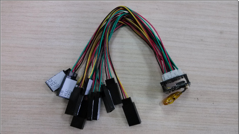
- Power: 3.7V lithium battery which can be charged by Micro USB
- Current: unknown
- Working temperature: -10℃~+70℃
- Interface: I2C,RS232
- Size: 22mm × 20mm
- 5 PWM channels
- 3 analog ports
- An Acceleration Sensor on the board
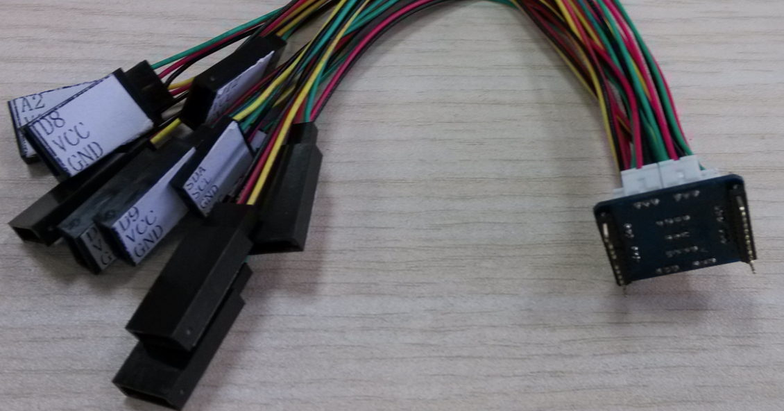 the ports can be clearly distinguished as the picture performanced. and once you have gotten a Nova, you can easily know which port is D13 and which one is A0, etc.
Now let's forget most of the limitation caused by the big sharp of any other controllers, this new product can provide a small size which only measures 22mm*20mm. This module can be seaily put in some small place and then work for you. And beacuse this module contains a battery, so you can let it alone and don't need to supply power through a long wire.
What's more, we had put a acceleration sensor on the board, so you can do more things with this product like vibration measurement, posture transportation and so on. And it can be more interesting when you try to controll your LEDs use the value measured by your acceleration sensor, the LEDs can show the moving of your board, it is cool.
The small size means less limitation, why not put it in your pocket or on your door, it can color your home and light your cloth.
You can get the pin out in the right image, and the way to use this module is as the same as Leonardo but be care that not all the pins were given for you because of the limitation of its small size. Before you use this product, you can look up the website http://arduino.cc/en/Main/ArduinoBoardLeonardo for details of the function of the pin you need. 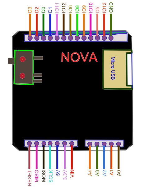
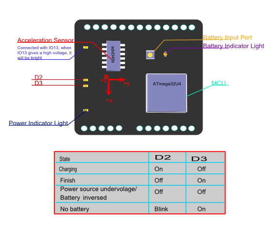
The code below shows how to make LEDs change their light between dark to bright circularly. And it can be more beautiful if your LEDs have different kinds of color.
// # Editor    :Holiday from DFRobot
// # Data      :08.06.2013

// # Product name:Nova
// # Product SKU:Unknown
// # Version : V2.0

// # Description:
// # This sample shows how to use the Nova for LED controlling

// # Connection:
// # LED1,LED2,LED3 ->D9,D10,D13 (Arduino)

void setup()
{
  pinMode(9,OUTPUT);
  pinMode(10,OUTPUT);
  pinMode(13,OUTPUT);
}
void loop()
{
  for (int i=0;i<255;i++)
  {
    analogWrite(9,i);                    //LEDs will be brighter with a rising "i"
    analogWrite(10,i);                   //"i" means the value of PWM
    analogWrite(13,i);
    delay(10);
  }
  delay(100);
  for(int i=255;i>0;i--)
  {
    analogWrite(9,i);                   //LEDs will be darker with a declining "i"
    analogWrite(10,i);                  //"i" means the value of PWM
    analogWrite(13,i);
    delay(10);
  }
}
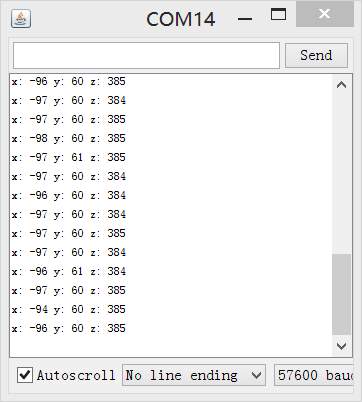
As there is an acceleration sensor on the board,we can do something more interesting. You need not change your connection because we will use it again. The code below can make LEDs show the posture of your board through adxl345b, which is the acceleration sensor mentioned previously.And you can check that whether you get the value of acceleration from serial.
// # Editor    :Holiday from DFRobot
// # Data      :08.06.2013

// # Product name:Nova
// # Product SKU:Unknown
// # Version : V2.0

// # Description:
// # This sample shows how to use the Nova for LED controlling

// # Connection:
// # LED1,LED2,LED3 ->D9,D10,D13 (Arduino)

#include <Wire.h>

#define DEVICE (0x53) // Device address as specified in data sheet

byte _buff[6];

char POWER_CTL = 0x2D;  //Power Control Register
char DATA_FORMAT = 0x31;
char DATAX0 = 0x32; //X-Axis Data 0
char DATAX1 = 0x33; //X-Axis Data 1
char DATAY0 = 0x34; //Y-Axis Data 0
char DATAY1 = 0x35; //Y-Axis Data 1
char DATAZ0 = 0x36; //Z-Axis Data 0
char DATAZ1 = 0x37; //Z-Axis Data 1

void setup()
{
  Wire.begin();        // join i2c bus (address optional for master)
  Serial.begin(57600);  // start serial for output. Make sure you set your Serial Monitor to the same!
  Serial.print("init");

  //Put the ADXL345 into +/- 4G range by writing the value 0x01 to the DATA_FORMAT register.
  writeTo(DATA_FORMAT, 0x01);
  //Put the ADXL345 into Measurement Mode by writing 0x08 to the POWER_CTL register.
  writeTo(POWER_CTL, 0x08);
  pinMode(9,OUTPUT);
  pinMode(10,OUTPUT);
  pinMode(13,OUTPUT);
}

void loop()
{
  readAccel(); // read the x/y/z tilt
  delay(500); // only read every 0,5 seconds
}

void readAccel() {
  uint8_t howManyBytesToRead = 6;
  readFrom( DATAX0, howManyBytesToRead, _buff); //read the acceleration data from the ADXL345

  // each axis reading comes in 10 bit resolution, ie 2 bytes.  Least Significat Byte first!!
  // thus we are converting both bytes in to one int
  int x = (((int)_buff[1]) << 8) | _buff[0];
  int y = (((int)_buff[3]) << 8) | _buff[2];
  int z = (((int)_buff[5]) << 8) | _buff[4];
  Serial.print("x: ");
  Serial.print( x );
  Serial.print(" y: ");
  Serial.print( y );
  Serial.print(" z: ");
  Serial.println( z );
  analogWrite(9,x);
  analogWrite(10,y);
  analogWrite(13,z);                          // change the luminance of LEDs which depends on the acceleration value
}

void writeTo(byte address, byte val) {
  Wire.beginTransmission(DEVICE); // start transmission to device
  Wire.write(address);             // send register address
  Wire.write(val);                 // send value to write
  Wire.endTransmission();         // end transmission
}

// Reads num bytes starting from address register on device in to _buff array
void readFrom(byte address, int num, byte _buff[]) {
  Wire.beginTransmission(DEVICE); // start transmission to device
  Wire.write(address);             // sends address to read from
  Wire.endTransmission();         // end transmission

  Wire.beginTransmission(DEVICE); // start transmission to device
  Wire.requestFrom(DEVICE, num);    // request 6 bytes from device

  int i = 0;
  while(Wire.available())         // device may send less than requested (abnormal)
  {
    _buff[i] = Wire.read();    // receive a byte
    i++;
  }
  Wire.endTransmission();         // end transmission
}
A couple reports indicate issues with the bootloader and a solution is to upload the latest leonardo bootloader to Nova. The procedure is simple, requiring only a ISP programmer. plug in the ISP wires and flash the leonardo bootloader onto the nova board again, unbricking the Nova.
On a side note, beware the battery connector, must be kept away from the pins on board, failing to do so could break the pins or even the controller if shorted. Electric tape on top of the pins could potentially help avoid this problem.
How to Use a Three-Axis Accelerometer for Tilt Sensing.
 shopping nova basic kit (a coin sized arduino compatible controller) (sku: kit0042)