Mini_Robot_chassis_Encoder_(SKU_SEN0116) - jimaobian/DFRobotWiki GitHub Wiki

Introduction
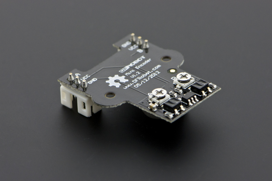
This encoder is matched with 2wd miniQ Robot chassis. AB two-phase pulse wave,measured by two infrared reflective sensor.These two sensor pulse waveform is close to a phase difference of 90 degrees, through the AB two-phase lead and lag of the waveform judged wheel forward rotation or the reverse. You can install it on the motor bracket or mini robot chassis to do the PID and position control.
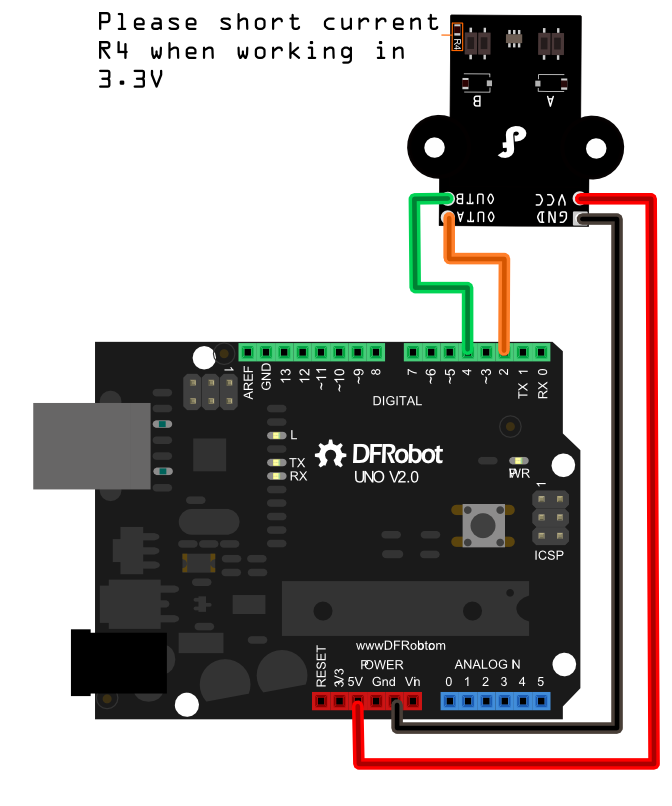
Note: Please short current R4 when working in 3.3V
Specification
- Working Voltage:3.3V or 5V
- Working Current:<14mA @5V
- Pulse Output:12 per revolution
- Compatibility:42mm x 19mm wheel
Encoder Connection Diagram

Sample Code
const byte encoder0pinA = 2;//A pin -> the interrupt pin 0
const byte encoder0pinB = 4;//B pin -> the digital pin 4
byte encoder0PinALast;
int duration;//the number of the pulses
boolean Direction;//the rotation direction


void setup()
{
  Serial.begin(57600);//Initialize the serial port
  EncoderInit();//Initialize the module
}

void loop()
{
  Serial.print("Pulse:");
  Serial.println(duration);
  duration = 0;
  delay(100);
}

void EncoderInit()
{
  Direction = true;//default -> Forward
  pinMode(encoder0pinB,INPUT);
  attachInterrupt(0, wheelSpeed, CHANGE);
}

void wheelSpeed()
{
  int Lstate = digitalRead(encoder0pinA);
  if((encoder0PinALast == LOW) && Lstate==HIGH)
  {
    int val = digitalRead(encoder0pinB);
    if(val == LOW && Direction)
    {
      Direction = false; //Reverse
    }
    else if(val == HIGH && !Direction)
    {
      Direction = true;  //Forward
    }
  }
  encoder0PinALast = Lstate;

  if(!Direction)  duration++;
  else  duration--;
}
FAQ
| '''Q1. '''I have a question about the encoder. In the process of adjusting the screws, I have turned a screw out of range and don't know which way to turn it back. Is there one direction i should turn it to 'start from zero'? |
'''A1. '''You can turn it in clockwise or reversely to adjust the resistance value, range 0-30KΩ. And the valid adjustable angle is 260°±20°. To make it easier to understand, it means if you rotate it in 360°, it will keep the same resistance value.
 get it from dfrobot store or dfrobot distributor.
category: Product Manual category: DFR Series category: Sensors