Micro_DC_Motor_with_Encoder SJ02_SKU__FIT0450 - jimaobian/DFRobotWiki GitHub Wiki

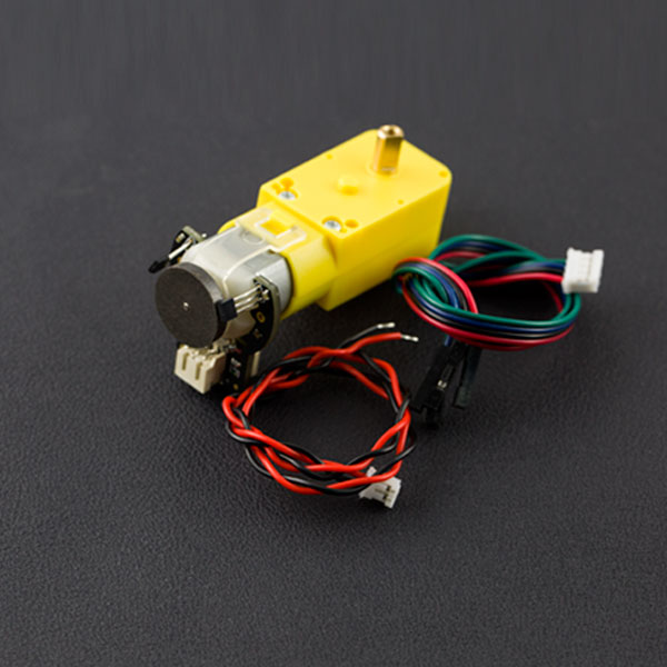
This is a new DFRobot micro DC geared motor with encoder. It is a motor with a 120:1 gearbox and an integrated quadrature encoder that provides a resolution of 16 pulse single per round. It means the motor could output 1920 within one round. With the arduino controller and motor drives, you can do something such as closed-loop PID control and PWM speed control. this motor is an ideal option for your mobile robot project. Copper output shaft, embedded thread, reinforced connector, it greatly extends the motor life, and the connection method is also very convenient.
- Gear ratio: 120:1
- No-load speed @ 6V: 160 rpm
- No-load speed @ 3V: 60 rpm
- No-load current @ 6V: 0.17A
- No-load current @ 3V: 0.14A
- Max Stall current: 2.8A
- Max Stall torque: 0.8kgf.cm
- Rated torque: 0.2kgf.cm
- Encoder operating voltage: 4.5~7.5V
- Motor operating voltage: 3~7.5V (Rated voltage 6V)
- Operating ambient temperature: -10~+60℃
 |
                                                  |-----------|--------------------------|------------------------------------------------------------------------------|
                                                  | **Grade** | **Name**                 | **Functional Description**                                                   |
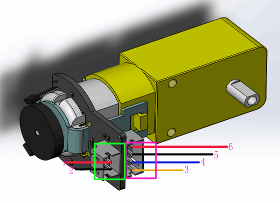
                                                  | 1         | Motor power supply pin + | 3-7.5V,Rated voltage6V                                                      |
                                                  | 2         | Motor power supply pin - |                                                                              |
                                                  | 3         | Encoder A phase output   | Changes square wave with the output frequency of Motor speed                 |
                                                  | 4         | Encoder B phase output   | Changes square wave with the output frequency of Motor speed(interrupt port) |
                                                  | 5         | Encoder supply GND       |                                                                              |
                                                  | 6         | Encoder supply +         | 4.5-7.5V                                                                     |  |
-
hardware
- DFRduino UNO x1
- DC power supply x1
- L298 x1
-
software
- Arduino IDE Download Arduino IDE
 |
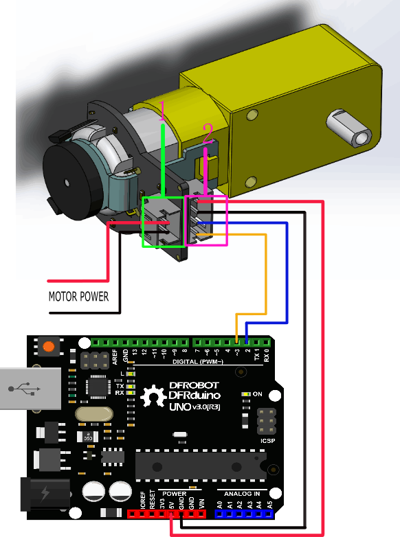
This tutorial is intended to use the encoder, Select D2 pin and D3 pin, Wherein D2 as an interrupt port, D3 as an input pin.. In practice, two pins need to ensure that one of pins must be an interrupt pin, and the other definable (see the interrupt port with different board).
====Interrupt Port with Different Board====
***Notcie:***attachInterrupt()  for example,with uno board, you want to use interrupt port 0(int.0). you should connect digital pin 2 with the board. so, the following code is only used in uno and mega2560. if you want to use Leonardo or Romeo, you should change digital pin 3 instead of digital pin 2.
See the link for details http://arduino.cc/en/Reference/AttachInterrupt
//The sample code for driving one way motor encoder
const byte encoder0pinA = 2;//A pin -> the interrupt pin 0
const byte encoder0pinB = 3;//B pin -> the digital pin 3
byte encoder0PinALast;
int duration;//the number of the pulses
boolean Direction;//the rotation direction


void setup()
{
  Serial.begin(57600);//Initialize the serial port
  EncoderInit();//Initialize the module
}

void loop()
{
  Serial.print("Pulse:");
  Serial.println(duration);
  duration = 0;
  delay(100);
}

void EncoderInit()
{
  Direction = true;//default -> Forward
  pinMode(encoder0pinB,INPUT);
  attachInterrupt(0, wheelSpeed, CHANGE);
}

void wheelSpeed()
{
  int Lstate = digitalRead(encoder0pinA);
  if((encoder0PinALast == LOW) && Lstate==HIGH)
  {
    int val = digitalRead(encoder0pinB);
    if(val == LOW && Direction)
    {
      Direction = false; //Reverse
    }
    else if(val == HIGH && !Direction)
    {
      Direction = true;  //Forward
    }
  }
  encoder0PinALast = Lstate;

  if(!Direction)  duration++;
  else  duration--;
}
Code 1 phenomenon: Explanation: The data output from the serial, when the motor forward, the output value> 0, when the motor reverse rotation, digital output <0. And The faster the motor speed, the greater the absolute value of number.


PID control: PID algorithm to control the motor speed by L298P DC motor driver board
- Motor power port is connected to the L298 drive motor M1 port
- Download and installArduino PID
//The sample code for driving one way motor encoder
#include <PID_v1.h>
const byte encoder0pinA = 2;//A pin -> the interrupt pin 0
const byte encoder0pinB = 3;//B pin -> the digital pin 3
int E_left =5; //The enabling of L298PDC motor driver board connection to the digital interface port 5
int M_left =4; //The enabling of L298PDC motor driver board connection to the digital interface port 4
byte encoder0PinALast;
double duration,abs_duration;//the number of the pulses
boolean Direction;//the rotation direction
boolean result;

double val_output;//Power supplied to the motor PWM value.
double Setpoint;
double Kp=0.6, Ki=5, Kd=0;
PID myPID(&abs_duration, &val_output, &Setpoint, Kp, Ki, Kd, DIRECT);

void setup()
{
  Serial.begin(9600);//Initialize the serial port
   pinMode(M_left, OUTPUT);   //L298P Control port settings DC motor driver board for the output mode
   pinMode(E_left, OUTPUT);
   Setpoint =80;  //Set the output value of the PID
   myPID.SetMode(AUTOMATIC);//PID is set to automatic mode
   myPID.SetSampleTime(100);//Set PID sampling frequency is 100ms
  EncoderInit();//Initialize the module
}

void loop()
{
      advance();//Motor Forward
      abs_duration=abs(duration);
      result=myPID.Compute();//PID conversion is complete and returns 1
      if(result)
      {
        Serial.print("Pluse: ");
        Serial.println(duration);
        duration = 0; //Count clear, wait for the next count
      }


}

void EncoderInit()
{
  Direction = true;//default -> Forward
  pinMode(encoder0pinB,INPUT);
  attachInterrupt(0, wheelSpeed, CHANGE);
}

void wheelSpeed()
{
  int Lstate = digitalRead(encoder0pinA);
  if((encoder0PinALast == LOW) && Lstate==HIGH)
  {
    int val = digitalRead(encoder0pinB);
    if(val == LOW && Direction)
    {
      Direction = false; //Reverse
    }
    else if(val == HIGH && !Direction)
    {
      Direction = true;  //Forward
    }
  }
  encoder0PinALast = Lstate;

  if(!Direction)  duration++;
  else  duration--;

}
void advance()//Motor Forward
{
     digitalWrite(M_left,LOW);
     analogWrite(E_left,val_output);
}
void back()//Motor reverse
{
     digitalWrite(M_left,HIGH);
     analogWrite(E_left,val_output);
}

void Stop()//Motor stops
{
     digitalWrite(E_left, LOW);
}
Code 2 phenomenon: Because the programmed PID is 80, the motor will stabilize at about 80 rpm, when the outside forces (such as motor drive voltage changes, the motor's resistance increases, etc) to change the speed, the program will be adjusted by PWM, and the rotational speed will stabilized at 80. For example, increasing the motor drive voltage, motor speed will drop a brief and then rise to 80, reducing the motor drive voltage, the motor speed will drop a short, and then up to 80.
- [Motor dimension drawing]
category: Product Manual category: FIT Series category: Motor