MCP3424_18 Bit_ADC 4_Channel_with_Programmable_Gain_Amplifier_(SKU_DFR0316) - jimaobian/DFRobotWiki GitHub Wiki

The module integrates MCP3432 A/D converter chip. The module can provide analog input function for Raspberry Pi and provide high accuracy analog input for Arduino.
MCP3424 is one of the low noise and high accuracy 18-Bit delta-sigma analog-to-digital (ΔΣ A/D) converter family members of the MCP342X series. Its characteristic is:
- Self calibration of internal offset and gain per each conversion.
- The user can select the PGA gain before the analog-to-digital conversion takes place. This allows the device to convert a very weak input signal with high resolution.
- The device have two conversion modes:
- (a)One-Shot mode: the device performs a single conversion and enters a low current standby mode automatically until it receives another conversion command.
- (b)Continuous mode: the conversion takes place continuously at the set conversion speed.
- Temperature Sensing with RTD, Thermistor, and Thermocouple
- Bridge Sensing for Pressure, Strain, and Force
- Weigh Scales
- Battery Fuel Gauges
- Operating Voltage: 2.7 - 5.5V
- Standy Current: 300nA (5V)
- Operating Temperature: -40°C ~ +125°C
- On-Board Voltage Reference: 2.048V ± 0.05%, Drift 15 PPM /°C
- On-Board Programmable Gain Amplifier (PGA): x1,x2,x4,x8
- Differential Input Full Scale Range: -2.048V / PGA ~ 2.048V / PGA (e.g., PGA=4, Range is -0.512 ~ 0.512V)
- Programmable Resolution: 12, 14, 16, 18bits
- Programmable Data Rate: 240, 60, 15, 3.75 SPS
- Gain Error: 0.05% (PGA = 1, 18bits)
- Offset Error: 15uV (PGA = 1, 18bits)
- Input Interface: 4 differential channels, PIN header of 2.54mm spacing
- Output Interface: I2C, PIN header of 2.54mm spacing
- Size: 27x16mm

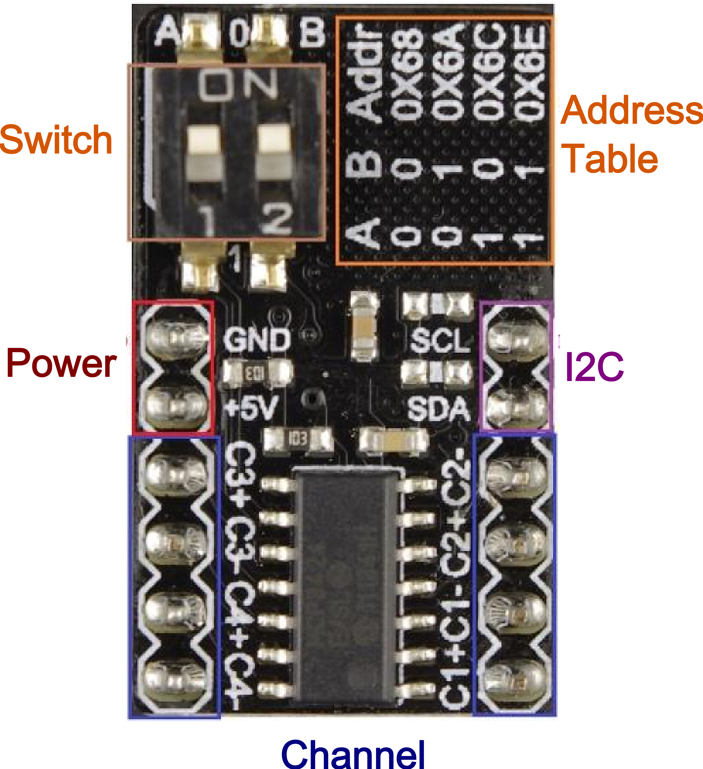
- Input and output pins showed in the diagram.
- Switch: set I2C address.
a) Target: Measure voltage by Arduino
b) Hardware List
- DF_UNO 1
- MCP3432 module 1
- Regulated power or AA battery 1
- Dupont wires
c) Software List
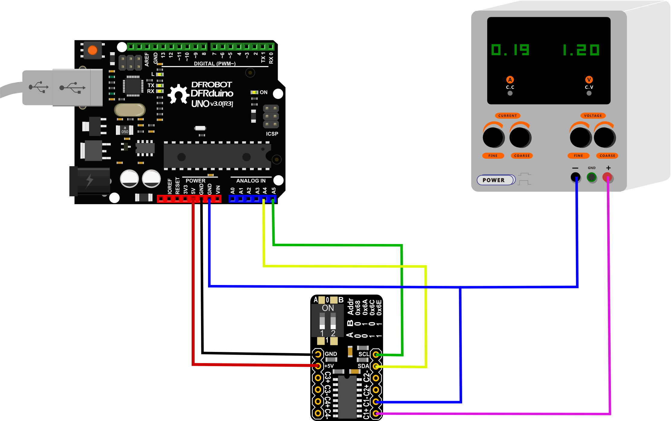
d) Connected diagram

e) Step by step
- Adjust voltage of Regulated Power to 0-2.085V, and then power on.
- Install Arduino MCP3424 library, see Install Arduino MCP3424 library
- Open Arduino IDE
- Upload code to UNO
 /* MCP 3424 version 1.2 example sketch OneShotConversion
 Written by B@tto
 Contact : [email protected]

 In this example, one conversion per second is performed on channel 1 and 16 bits resolution.
 A new conversion has to be initiated by the user
 */


 #include <Wire.h>
 #include <MCP3424.h>

 MCP3424 MCP(0x68);   // Declaration of MCP3424 with Address of I2C

 long Voltage;

 void setup(){

   Serial.begin(9600);
   MCP.Configuration(1,16,0,1); // Channel 1, 16 bits resolution, one-shot mode, amplifier gain = 1

 }

 void loop(){

   MCP.NewConversion();    // New conversion is initiated

   Voltage=MCP.Measure();  // Measure, note that the library waits for a complete conversion

   Serial.print("Voltage = ");
   Serial.print(Voltage);
   Serial.println("uV");  // unit: microVolt

   delay (1000);

 }
f) Result
- Open Ardino serial monitor, the voltage will be displayed.
a) Target: Measure voltage by RPi
b) Hardware List
- Raspberry Pi B+ 1
- Regulated power or AA battery 1
- Dupont wires
c) Software List
d) Connected Diagram: refer to the previous tutorial, connect I2C and power in the GPIO of RPi to the MCP3424 module.
e) Step by step: refer to the "Readme" of the Driver.
 Shopping [ (SKU: DFR0316)]