LED_Keypad_Shield_V1.0_SKU_DFR0382 - jimaobian/DFRobotWiki GitHub Wiki

Introduction
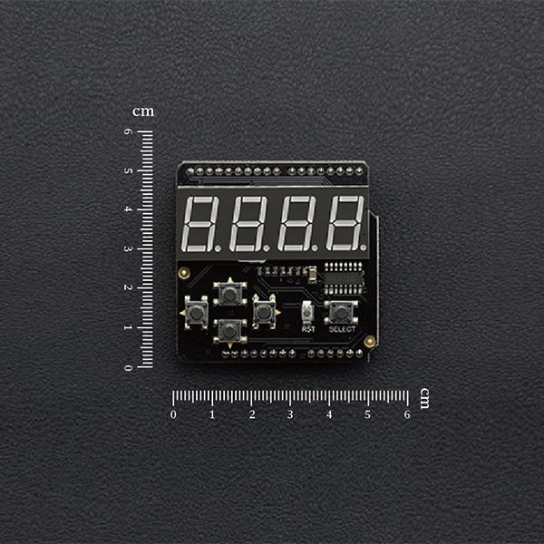
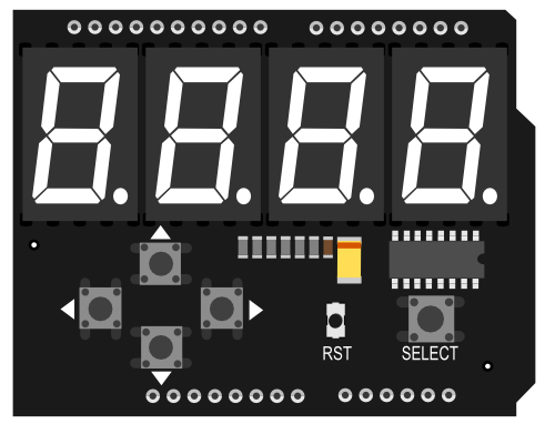
The LED Keypad Shield is an Arduino expansion shield with a 4 digit 8 segment digital tube display (common cathode). It has 5 buttons that can be used as menu select buttons or control buttons. It uses I2C to drive the digital tube for an easy user experience.
Specification
- Arduino compatible
- Working voltage: 5V
- 4 digit 8 segment common cathode digital tube (0.56 inch)
- 5 input buttons (Driving pin: A0)
- Size: 53 * 54mm/2.05 * 2.12inches
Pin Definition
 |
                                       |--------------|-------------------------------------|--------------|---------------------------------------------------------------------------------------------------|---------|------------------------------------|---------|-----------------------------------------------------------------------|-----|-------|
                                       | **PIN Name** | **Description** |- align = "center" | Analog Pin 0 | Button (select, top, right, bottom, left) |- style="background-color:\#B7DDE8; " align = "center" | SCL(A5) | I2C clock line |- align = "center" | SDA(A4) | I2C data line |- style="background-color:\#B7DDE8; " align = "center" | RST | Reset |  |
Tutorial
| #### Requirements |
- Hardware
- UNO x1
- LED Keypad Shield x1
- Software
- Arduino IDE V1.6.5 Click to Download Arduino IDE from Arduino®
Connection Diagram
This module's pin alignments allow it to stack directly on top of an Arduino UNO or similar microcontroller
Sample Code
Please install the following libraries for this code to function.
LedKeypad Arduino library About Library installation.
#include <LedKeypad.h>

char brightness =0;
char buf[5]="2456";

void setup() {
  ledkeypad.begin(); /*Enable*/
  ledkeypad.setBrightness(0);/*Sets the brightness level*/
  ledkeypad.display(2015);/*Display data*/
  delay(5000);
  ledkeypad.display(buf);/*Display character for testing*/
  for(int i=0;i<4;i++){/*for testing*/
    ledkeypad.dotShow(i);
    delay(1000);
    ledkeypad.dotVanish(i);
  }
}

void loop() {
  unsigned char keyValue=0;
  keyValue = ledkeypad.getKey();/*Get key value*/
  switch(keyValue){
    case KEY_DOWN:
      buf[0]++;
      if(buf[0] > '9')
        buf[0] = '0';
      ledkeypad.display(0,buf[0]);
      break;

    case KEY_LEFT:
      buf[1]++;
      if(buf[1] > '9')
        buf[1] = '0';
      ledkeypad.display(1,buf[1]);
      break;

    case KEY_UP:
      buf[2]++;
      if(buf[2] > '9')
        buf[2] = '0';
      ledkeypad.display(2,buf[2]);
      break;

    case KEY_RIGHT:
      buf[3]++;
      if(buf[3] > '9')
        buf[3] = '0';
      ledkeypad.display(3,buf[3]);
      break;

    case KEY_SELECT:
      brightness++;
      if(brightness > 7)
        brightness = 0;
      ledkeypad.setBrightness(brightness);
      break;

    default:
      break;
 }
}
Result
The sample code is a simple clock for the module. Using the input buttons the time can be adjusted. Key functions are as follows:
| button | function |
|---|---|
| down | The first digital tube +1 |
| left | The sencond digital tube +1 |
| up | The third digital tube +1 |
| right | The fourth digital tube +1 |
| select | adjusting brightness |
More
 get it from dfrobot store or dfrobot distributor.