GSM_Module_V2.0_(SKU_TEL0051) - jimaobian/DFRobotWiki GitHub Wiki
This is a GPS/GPRS/GSM shield from DFRobot. This shield with a Quad-band GSM/GPRS engine works on frequencies EGSM 900MHz/DCS 1800MHz and GSM850 MHz/PCS 1900MHz. It also supports GPS technology for satellite navigation. It's possible for your robot and control system to send messages and use the GSM network. It is controlled via AT commands(GSM07.07 ,07.05 and SIMCOM enhanced AT Commands). And the design of this shield allows you to drive the GSM & GPS function directly with the computer and the Arduino Board. It includes a high-gain SMD antenna for GPS & GSM. This GPS/GPRS/GSM shield uses an embedded SIM548C chip from SIMCom.Featuring an industry-standard interface and GPS function, the combination of both technologies allows goods, vehicles and people to be tracked seamlessly at any location and anytime with signal coverage.
- Power supply: 6-12v
- Low power consumption (100mA@7v - GSM mode)
- Quad-Band 850/900/18001900MHz
- GPRS multi-slot class 10
- Support GPS technology for satellite navigation
- Embeded high-gain SMD antennas for GPS & GSM
- Directly support 4*4 button pad
- USB/Arduino control switch
- Size: 70x55mm
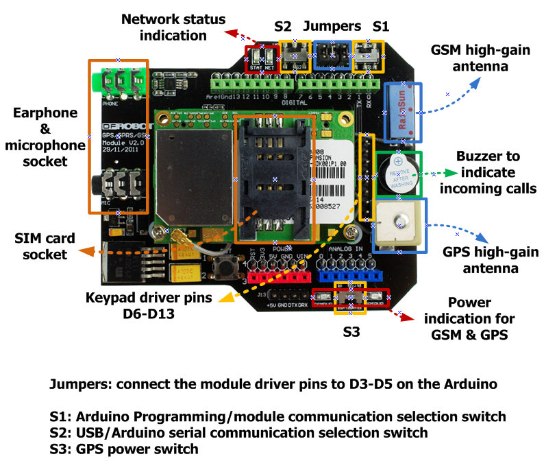 More details about switches:
*Switch S1: PC upload program to Arduino board/PC communicates with GPS/GPRS/GSM Module( Arduino programming/module communication).
- '''Switch S2: '''GPS/GPRS/GSM Module directly connects with PC through USB port or module communicates with Arduino board, which communicates with PC(USB/Arduino serial communication).
- Switch S3: GPS power supply to be on/off(GPS power switch).
The hardware requirements:
- Arduino Uno
- GPS/GPRS/GSM Module V2.0
- SIM Card
- Earphone & Microphone
- External power supply via the power jack
it is recommended you to supply 7~12v power via the power jack. When using the GSM mode, the module requires an external power. But the power consumption is not high,just 200mA@7v, when calling.
Module driver pin jumpers: Applying the Module Pin Jumpers(J10-J12) will allocate Pin 3,4,5 for driving the module. Removing the jumpers will release the above Pins, and you could connect the driver pins to the other digital pins on your board to avoid the pin conflict.
Hardware Connection photo: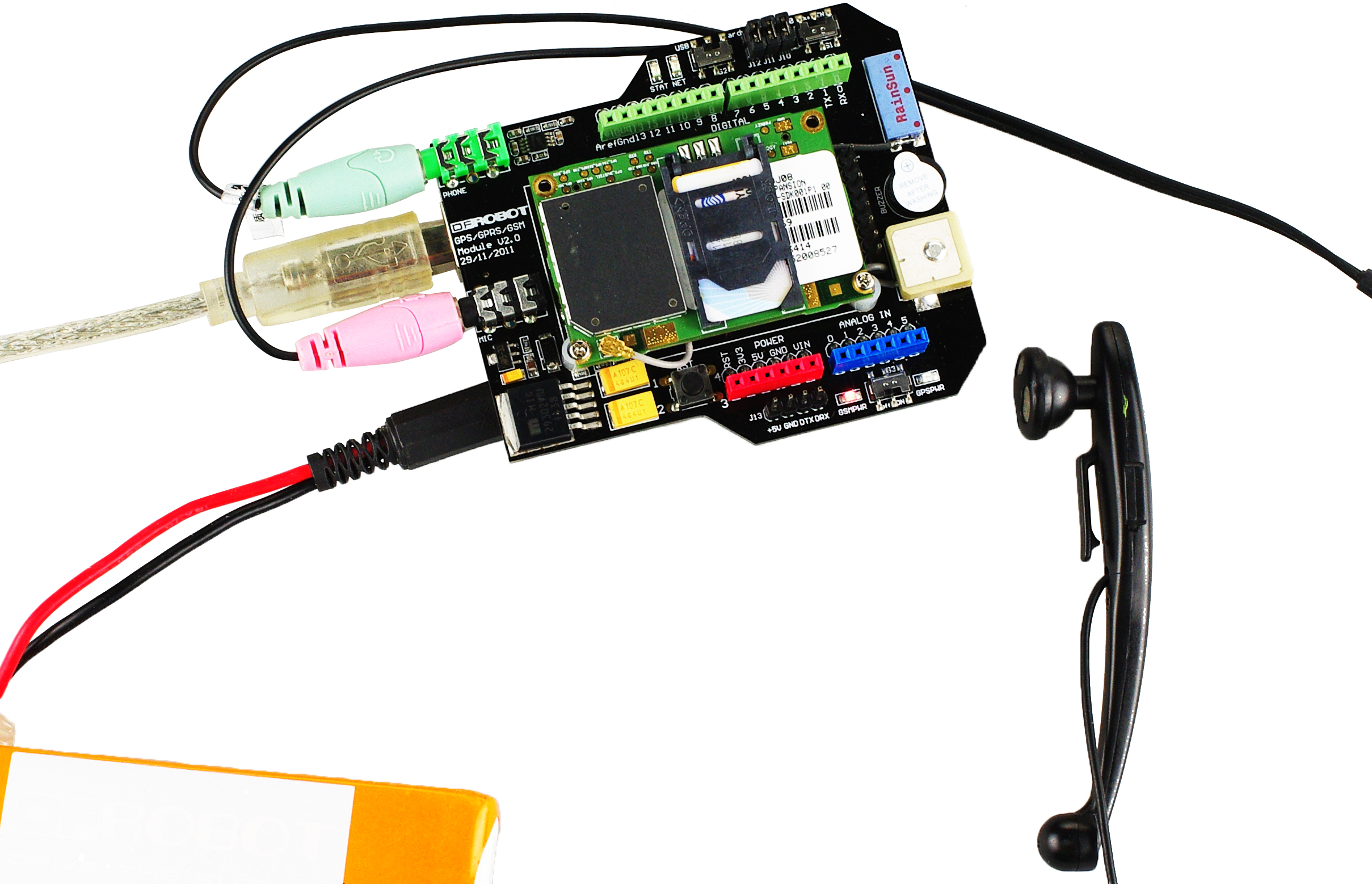
Following the steps included in the sketch below first! The Sketch for GSM mode:
// #
// # Editor     : Lauren from DFRobot
// # Date       : 23.05.2012
// # E-Mail : [email protected]

// # Product name: GPS/GPRS/GSM Module V2.0
// # Product SKU : TEL0051
// # Version     : 0.1

// # Description:
// # The sketch for driving the gsm mode via the USB interface

// # Steps:
// #        1. Turn the S1 switch to the EN(right side)
// #        2. Upload the sketch to the Arduino board
// #        3. Turn the S1 switch to the communication mode(left side)
// #        4. Turn the S2 switch to the USB side(left side)
// #        5. send AT commands via the Arduino Serial monitor

// #        wiki link- http://www.dfrobot.com/wiki/index.php?title=GPS/GPRS/GSM_Module_V2.0

byte gsmDriverPin[3] = {
  3,4,5};//The default digital driver pins for the GSM and GPS mode
//If you want to change the digital driver pins
//or you have a conflict with D3~D5 on Arduino board,
//you can remove the J10~J12 jumpers to reconnect other driver pins for the module!


void setup(){
  InitGsmMode();
}

void InitGsmMode(){
  //Init the driver pins for GSM function
  for(int i = 0 ; i < 3; i++){
    pinMode(gsmDriverPin[i],OUTPUT);
  }

  digitalWrite(3,LOW);//Enable the GSM mode
  digitalWrite(4,HIGH);//Disable the GPS mode
  //Output GSM Timing
  digitalWrite(5,HIGH);
  delay(1500);
  digitalWrite(5,LOW);
}

void loop(){
  delay(100);
}- If your module works, the indicator LEDs beside the switch S2 will light up, this means that the module is running correctly. The LED marked "NET" is used to drive a network status indication LED. The working state of this LED is listed below.
- Send the AT commands to the module by using Coolterm(or use the Arduino serial monitor).
Note: If you want to program the Arduino, please disconnect the coolterm to release the communication port.
| State | The GSM part of SIM548C function |
| Off | The GSM part of the module is not running |
| 64ms On/ 800ms Off | The GSM part of the module does not find the network |
| 64ms On/ 3,000ms Off | The GSM part of the module found the network |
| 64ms On/ 300ms Off | GPRS communication |
Default baudrate: 9600
Please do some settings as #Recommended settings before connection.If have trouble sending Ctrl+Z, please refers to #Ways to send Ctrl +Z in Coolterm 
Signal strength test with on-chip antenna:
Sending AT command for signal quantity report AT+CSQ through serial port terminal application, will receive signal strength as below.
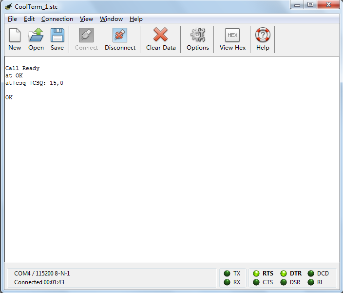 The returned data “15,0”, the first value “15” means the signal strength is:
| Value | Signal Strength |
|---|---|
| 0 | -113dBm or less |
| 1 | -111dBm |
| 2~30 | -109~-53dBm |
| 31 | -51dBm or greater |
| 99 | not know or not detectable |
The later value “0” means channel bit error rate.
Signal strength test with external antenna:

-
AT+=? : Test command
The mobile equipment returns the list of parameters and value ranges set with the corresponding Write command or by internal processes.
-
AT+? : Read command
This command returns the currently set value of the parameter or parameters
-
AT+=<..> : Write command
This command sets the user-definable parameter values.
-
AT+ : Execution command
This execution command reads non-variable parameters affected by internal processes in the GSM engine
-
AT : Test the serial communication.if it works,get "ok" as the picture show.
-
ATD; : Dial a number
-
ATA : Answer an incoming call
-
ATH : Disconnect existing connection
-
AT+UART : Configure dual serial port mode
-
AT+CSQ : Signal quality report
-
AT+CMGF : Select sms messages format
-
AT+CMGS : Send sms message
- After you input the sms, press 'ctrl-z'[HEX:0x1A]to send the message.
- Press 'ESC' to quit without sending.
-
AT+CNMI : New sms message indications
-
AT+CLVL : Loud speaker volume level
-
AT+CRSL : Ringer sound level
-
AT+CMIC : Change the microphone gain level
For more detail AT commands, please check the document here!
The hardware requirements:
- Arduino Uno
- GPS/GPRS/GSM Module V2.0
- External power supply via the power jack
We recommend you to supply 7~12v power via the power jack. When using the GPS mode, the module requires an external power. But the power consumption is not high, just [email protected] Module driver pin jumpers: Applying the Module Pin Jumpers(J10-J12) will allocate Pin 3,4,5 for driving the module. Removing the jumpers will release the above Pins, Hardware Connection photo:
- After turn switch s3 on (the right side), the GPSPWR led will be lit.
- In this mode, switch s2 is on left side. The GPS module communicates directly with PC. The serial port terminal application will show the data sent out by GPS module.
'''The Sketch for GPS USB mode: '''Following the steps included in sketch below first!
// #
// # Editor     : Lauren from DFRobot
// # Date       : 23.05.2012
// # E-Mail : [email protected]

// # Product name: GPS/GPRS/GSM Module V2.0
// # Product SKU : TEL0051
// # Version     : 0.1

// # Description:
// # The sketch for driving the gps mode via the USB interface

// # Steps:
// #        1. Turn the S1 switch to the EN(right side)
// #        2. Upload the sketch to the Arduino board
// #        3. Turn the S1 switch to the communication mode(left side)
// #        4. Turn the S2 switch to the USB side(left side)
// #        5. Turn the S3 switch to the ON side(right side)
// #        5. get the information from the module via the Arduino Serial monitor(baud rate:4800)
// #        For more detail information, please check the product wiki page.~.

// #        Wiki link - http://www.dfrobot.com/wiki/index.php?title=GPS/GPRS/GSM_Module_V2.0

byte gsmDriverPin[3] = {
  3,4,5};//The default digital driver pins for the GSM and GPS mode
//If you want to change the digital driver pins
//or you have a conflict with D3~D5 on Arduino board,
//you can remove the J10~J12 jumpers to reconnect other driver pins for the module!


void setup(){
  InitGpsMode();
}

void InitGpsMode(){
  //Init the driver pins for GSM function
  for(int i = 0 ; i < 3; i++){
    pinMode(gsmDriverPin[i],OUTPUT);
  }
  digitalWrite(3,HIGH);//Disable the GSM mode
  digitalWrite(4,LOW);//Enable the GPS mode
}

void loop(){
  delay(1000);
}
Serial communication
Default baudrate: 4800
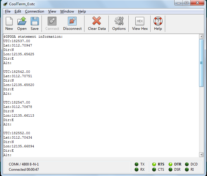
Coolterm(or Arduino serial monitor) is the recommended serial port terminal application. After serial port is successfully connected with PC in Coolterm, GPS module will send out data continuously as below: 
For location of the data received, please refer to Location Mapping (GPRMC)
- After turn switch s3 on (the right side), the GPSPWR led will be lit.
- In this mode, switch s2 is on right side. The GPS module communicates with Arduino board, and Arduino board communicates with PC. The serial port terminal application will show preliminary processed data from Arduino board, which gets the data from GPS module.
'''The Sketch for GPS mode via Arduino board: '''Following the steps included in sketch below first!
// #
// # Editor     : Lauren from DFRobot
// # Date       : 23.05.2012
// # E-Mail : [email protected]

// # Product name: GPS/GPRS/GSM Module V2.0
// # Product SKU : TEL0051
// # Version     : 0.1

// # Description:
// # The sketch for driving the gps mode via the Arduino TTL interface

// # Steps:
// #        1. Turn the S1 switch to the EN(right side)
// #        2. Upload the sketch to the Arduino board
// #        3. Turn the S1 switch to the communication mode(left side)
// #        4. Turn the S2 switch to the Arduino side(right side)
// #        5. Turn the S3 switch to the ON side(right side)
// #        5. get the information from the module via the Arduino Serial monitor(baud rate:4800)
// #        For more detail information, please check the product wiki page.~.

// #        wiki link - http://www.dfrobot.com/wiki/index.php?title=GPS/GPRS/GSM_Module_V2.0

byte gsmDriverPin[3] = {
  3,4,5};//The default digital driver pins for the GSM and GPS mode
//If you want to change the digital driver pins
//or you have a conflict with D3~D5 on Arduino board,
//you can remove the J10~J12 jumpers to reconnect other driver pins for the module!


void setup()
{
  InitGpsMode();//Init the module to the GPS mode

  Serial.begin(4800);//Init the serial baudrate
  Serial.println("$GPGGA statement information: ");
}

void InitGpsMode(){
  //Init the driver pins for GSM function
  for(int i = 0 ; i < 3; i++){
    pinMode(gsmDriverPin[i],OUTPUT);
  }
  digitalWrite(3,HIGH);//Disable the GSM mode
  digitalWrite(4,LOW);//Enable the GPS mode
}

void loop()
{
  while(1)  //get the GPS datas and print them to the Arduino Serial monitor
  {
    Serial.print("UTC:");
    UTC();
    Serial.print("Lat:");
    latitude();
    Serial.print("Dir:");
    lat_dir();
    Serial.print("Lon:");
    longitude();
    Serial.print("Dir:");
    lon_dir();
    Serial.print("Alt:");
//    altitude();
    Serial.println(' ');
    Serial.println(' ');
  }
}


double Datatransfer(char *data_buf,char num)//convert the data to the float type
{                                           //*data_buf:the data array
                                            //the number of the right of a decimal point
  double temp=0.0;
  unsigned char i,j;

  if(data_buf[0]=='-')//
  {
    i=1;
    //process the data array
    while(data_buf[i]!='.')
      temp=temp*10+(data_buf[i++]-0x30);
    for(j=0;j<num;j++)
      temp=temp*10+(data_buf[++i]-0x30);
    //convert the int type to the float type
    for(j=0;j<num;j++)
      temp=temp/10;
    //convert to the negative number
    temp=0-temp;
  }
  else//for the positive number
  {
    i=0;
    while(data_buf[i]!='.')
      temp=temp*10+(data_buf[i++]-0x30);
    for(j=0;j<num;j++)
      temp=temp*10+(data_buf[++i]-0x30);
    for(j=0;j<num;j++)
      temp=temp/10 ;
  }
  return temp;
}

char ID()//Match the ID commands
{
  char i=0;
  char value[6]={
    '$','G','P','G','G','A'    };//match the gps protocol
  char val[6]={
    '0','0','0','0','0','0'    };

  while(1)
  {
    if(Serial.available())
    {
      val[i] = Serial.read();//get the data from the serial interface
      if(val[i]==value[i])   //Match the protocol
      {
        i++;
        if(i==6)
        {
          i=0;
          return 1;//break out after get the command
        }
      }
      else
        i=0;
    }
  }
}

void comma(char num)//get ','
{
  char val;
  char count=0;//count the number of ','

  while(1)
  {
    if(Serial.available())
    {
      val = Serial.read();
      if(val==',')
        count++;
    }
    if(count==num)//if the command is right, run return
      return;
  }
}

void UTC()//get the UTC data -- the time
{
  char i;
  char time[9]={
    '0','0','0','0','0','0','0','0','0'
  };
  double t=0.0;

  if(ID())//check ID
  {
    comma(1);//remove 1 ','
    //get the datas after headers
    while(1)
    {
      if(Serial.available())
      {
        time[i] = Serial.read();
        i++;
      }
      if(i==9)
      {
        i=0;
        t=Datatransfer(time,2);//convert data
        t=t+80000.00;//convert to the chinese time GMT+8 Time zone
        Serial.println(t);//Print data
        return;
      }
    }
  }
}
void latitude()//get latitude
{
  char i;
  char lat[10]={
    '0','0','0','0','0','0','0','0','0','0'
  };

  if( ID())
  {
    comma(2);
    while(1)
    {
      if(Serial.available())
      {
        lat[i] = Serial.read();
        i++;
      }
      if(i==10)
      {
        i=0;
        Serial.println(Datatransfer(lat,5),5);//print latitude
        return;
      }
    }
  }
}
void lat_dir()//get dimensions
{
  char i=0,val;

  if( ID())
  {
    comma(3);
    while(1)
    {
      if(Serial.available())
      {
        val = Serial.read();
        //Serial.println(val,BYTE);//print dimensions
        Serial.println(val);//print dimensions
        i++;
      }
      if(i==1)
      {
        i=0;
        return;
      }
    }
  }
}
void longitude()//get longitude
{
  char i;
  char lon[11]={
    '0','0','0','0','0','0','0','0','0','0','0'
  };

  if(ID())
  {
    comma(4);
    while(1)
    {
      if(Serial.available())
      {
        lon[i] = Serial.read();
        i++;
      }
      if(i==11)
      {
        i=0;
        Serial.println(Datatransfer(lon,5),5);//print longitude
        return;
      }
    }
  }
}

void lon_dir()//
{
  char i=0,val;

  if(ID())
  {
    comma(5);
    while(1)
    {
      if(Serial.available())
      {
        val = Serial.read();
        //Serial.println(val,BYTE);
        Serial.println(val);
        i++;
      }
      if(i==1)
      {
        i=0;
        return;
      }
    }
  }
}

void altitude()//get altitude data
{
  char i,flag=0;
  char alt[8]={
    '0','0','0','0','0','0','0','0'
  };

  if( ID())
  {
    comma(9);
    while(1)
    {
      if(Serial.available())
      {
        alt[i] = Serial.read();
        if(alt[i]==',')
          flag=1;
        else
          i++;
      }
      if(flag)
      {
        i=0;
        Serial.println(Datatransfer(alt,1),1);//print altitude data
        return;
      }
    }
  }
}
Serial communication
Default baudrate: 4800
Settings below is recommended 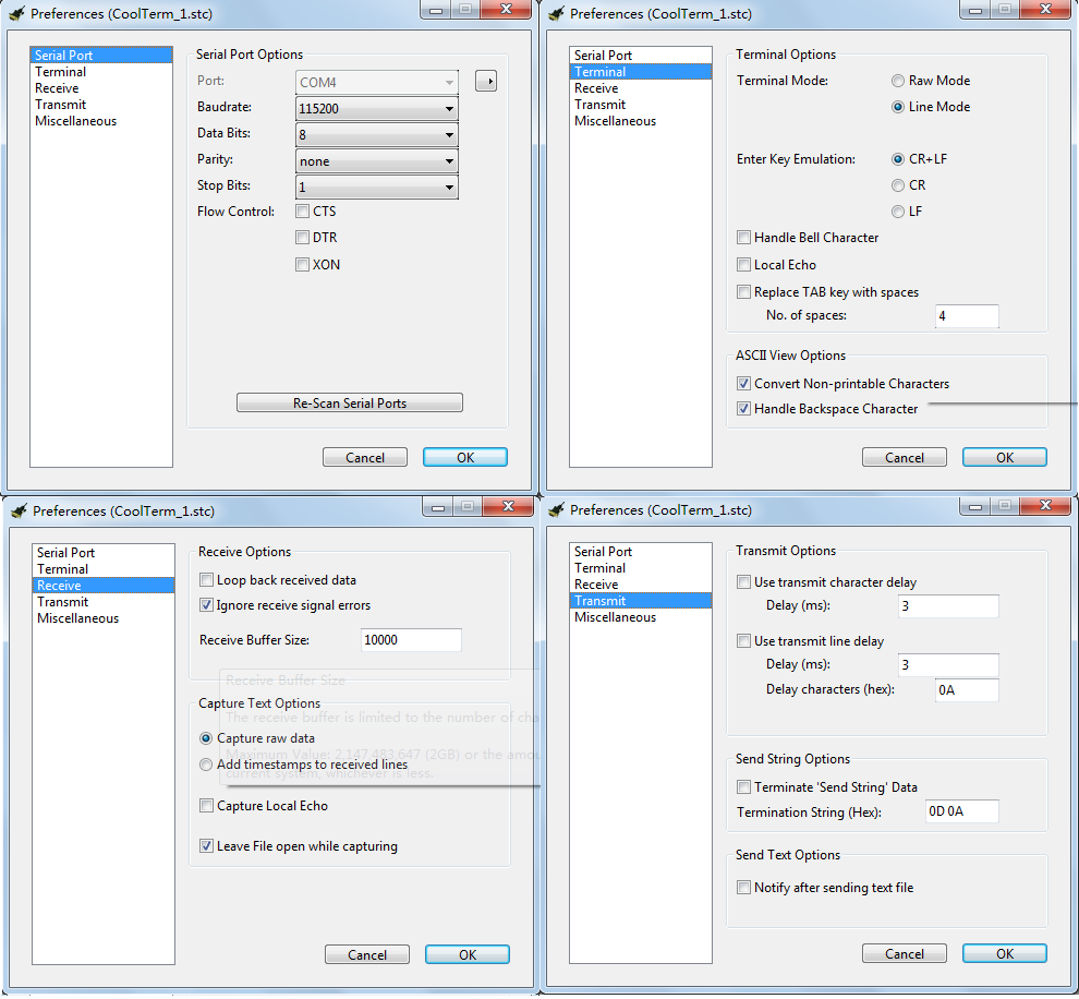
After the network indication LED showing GSM module has found the network, we can use it to send out message.
Setp 1: Set the system to text mode(as opposed to PDU mode) with command AT+CMGF=1(type "AT+CMGF=1" in the input line, then press KEY), you will get response as below.  step 2: set message receiver number with command at+cmgs="number"(replace number with your destination number),after pressing key, it will show as follow
  step 3: type in you message content, end with pressing key.
  step 4: send ctrl character ctrl+z to verify your message sending (just pressing ctrl and z simultaneously, key is not need after that).if it send out successfully, it will show as below.
  ====Ways to send Ctrl +Z in Coolterm==== '''1. '''After typing the message text, press enter key, it will show:
Then, in the input area, pressing Ctrl+Z will send out the single ctrl character successfully as below:
 '''2. '''ctrl characters can also be sent out in their hexadecimal format, in which form 1a is the value of ctrl+z:
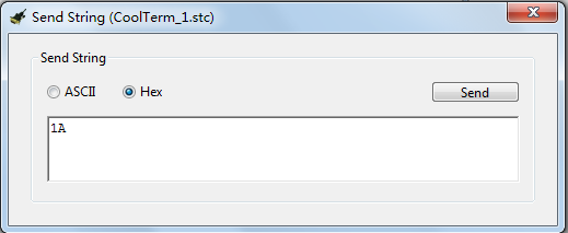
**1.**Serial connection errs. When connecting to PC, serial port terminal application occasionally warns “A Serial Port Err Occur 103: No Stop Bit Received” or ” A Serial Port Err Occur 104: stop bit received too early” A: set Coolterm in options-receive-ignore receiving signal err to ignore connection err and it will reconnect automatically. **2.**Serial port terminal application warns “Normal power down” when reconnect after disconnect, and Network indication LEDs both turn off. A: Choose disconnect, and connect again The Arduino board will reset at every connection to PC. During resetting, the Arduino board will emit a low pulse to pin PWRKEY of GPS module. So if GPS module is already on before connection, the low pulse will switch it off, if not, the pulse will switched it on. **3.**Serial port terminal application send out all the strings on the screen after pressing Ctrl+Z, when trying to send message in GSM USB mode. *'A: **It is possible to send Ctrl characters when the terminal is set to Line Mode. We can choose the Line Mode in options-terminal-terminal mode, or we can send the Ctrl character though sending string box of Coolterm in hexadecimal format. Please refer to Ways to send Ctrl +Z in Coolterm. **4.**Restart the serial port terminal application always works for other troubles. *Updating'!
*Arduino GSM library is a very complete GSM library for Arduino.
 shopping gps/gprs/gsm module v2.0 (sku:tel0051)
category: Product Manual category: TEL Series