GPIO_Shield_for_Arduino_V1.0_SKU__DFR0334 - jimaobian/DFRobotWiki GitHub Wiki
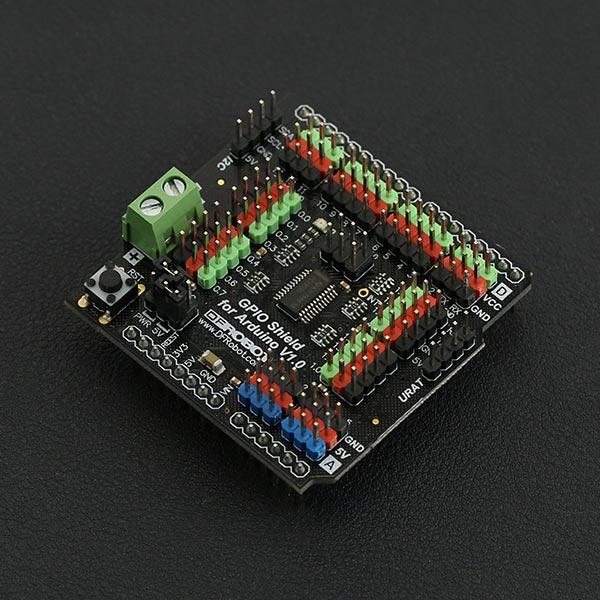
An Arduino UNO has a limited number of GPIO pins - but what if it is not enough? The GPIO expansion shield specifically designed for Arduino UNO-type boards. This shield greatly expands the GPIO resources to 36 pins in total, including 14 digital pins, 6 analog pins and 16 I2C pins. In addition digital and analog pins include the DFRobot "Gravity" interface, giving you in-line power and ground pins and saving you having to connect millions of jumper wires for a single sensor.
- Arduino Digital Pins: 14, D0 - D13
- Arduino Analog Pins: 6, A0 ~ A5
- IIC - GPIO Digital Pins: 16, P0.0 ~ P0.7; P1.0 ~ P1.7
- IIC Port: 1
- UART Port: 1
- Power Supply: 5 VDC / External Power Supply (jump cap switch)
- Reset Button: 1
- Dimensions: 53.34 x 54.48 mm / 2.1 x 2.14 inches
- Weight: 30g
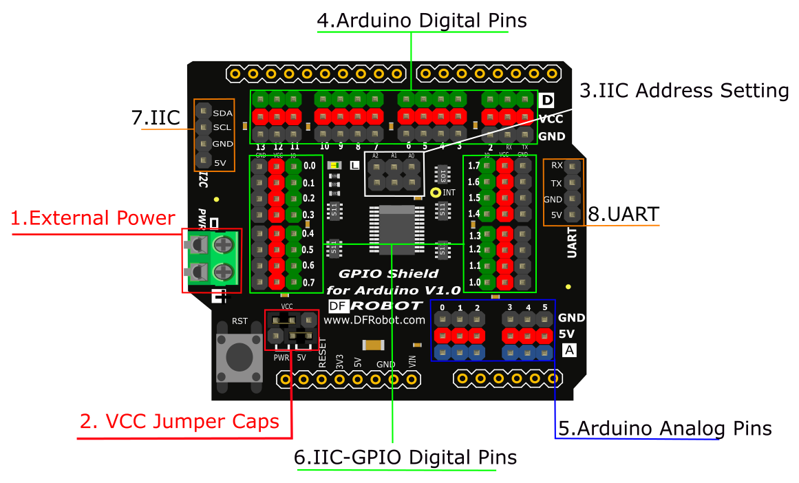 |
                                                                                        |---------|-------------------------------|-----------------------------------------------------|
                                                                                        | **Num** | **Name**                      | **Description**                                     |
                                                                                        | 1       | External Power                | 5 VDC                                               |
                                                                                        | 2       | VCC Jumper Caps               | Choose to power from board or shield external power |
                                                                                        | 3       | PCA9555DB IIC Address Setting | Set PCA9555DB I2C Address 0x20~0x27                 |
                                                                                        | 4       | Arduino Digital I/O Pins      | D0~D13                                              |
                                                                                        | 5       | Arduino Analog input Pins     | A0~A5                                               |
                                                                                        | 6       | IIC to GPIO Digital Pins      | P0.0~P0.7; P1.0~P1.7                                |
                                                                                        | 7       | IIC Port                      | IIC Communication                                   |
                                                                                        | 8       | UART Port                     | UART Communication                                  |  |
- Config PCA9555 IIC Address with A0
A2 Jumper Caps (0x200x27)
Plug = 0 Unplug = 1
| A2 | A1 | A0 | I2C Address |
| 0 | 0 | 0 | 0x20 (Default) |
| 0 | 0 | 1 | 0x21 |
| 0 | 1 | 0 | 0x22 |
| 0 | 1 | 1 | 0x23 |
| 1 | 0 | 0 | 0x24 |
| 1 | 0 | 1 | 0x25 |
| 1 | 1 | 1 | 0x26 |
| 1 | 1 | 1 | 0x27 |
"D": represents digital signal "A": represents analog signal
One of the biggest benefits of the I/O expansion shield is more power and GND pins, allowing you to connect more sensors.
* Green: digital signal
* Blue: analog signal
* Red: VCC
* Black: GND
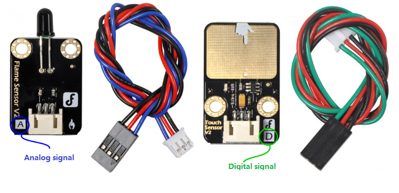
- This is DFRobot's Gravity Interface. Digital and analog connections are easy to recognize and support most of DFRobot's I/O expansion shields and modules. Search "Gravity" in the DFRobot store to find compatible modules.
There are two Jump caps, you can change the position of two caps for the different VCC power input. See the following schematic for details: 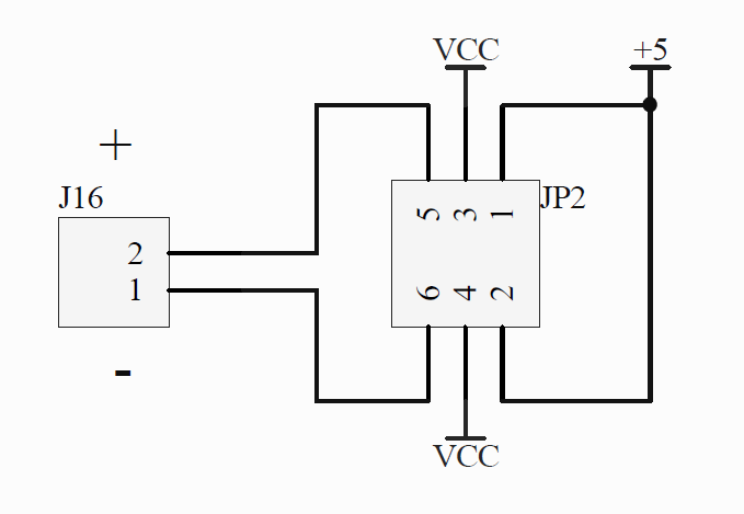 The middle pin is the shield VCC pin.
If you connect caps on the left side, VCC pins get power from the shield external port;
If you connect caps on the right side, VCC pins get power from the board 5V port;
This is suitable for some applications that require greater current.
-
Hardware
- DFRduino UNO x1
- GPIO Shield for Arduino x1
- Button module
- LED module
-
Software
- Arduino IDE Click to Download Arduino IDE from Arduino®
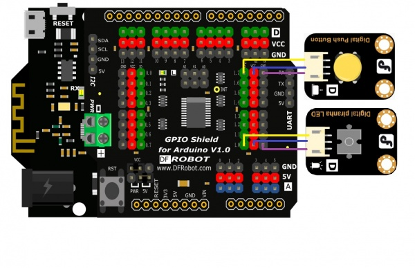
In this section, we will use an Arduino library written by nicoverduin Github Library. About Library installation.
#if defined(ARDUINO) && ARDUINO >= 100
#include "Arduino.h"
#else
#include "WProgram.h"
#endif

#include "clsPCA9555.h"
#include "Wire.h"


PCA9555 ioport(0x20);

void setup()
{
  ioport.pinMode(8, OUTPUT); //Set GPIOs pinMode LED
  ioport.pinMode(15, INPUT);  //Button
}

void loop()
{
  if (ioport.digitalRead(ED15) == LOW) {
    ioport.digitalWrite(8, LOW);                  //Turn off Led
  }

  if (ioport.digitalRead(ED15) == HIGH) {
    ioport.digitalWrite(8, HIGH);                 //Turn on Led
  }

} For any questions/advice/cool ideas to share, please visit DFRobot Forum.
Schematic
Layout
PCA9555 Datasheet
SVG files
 shopping from dfrobot store or dfrobot distributor.